Issue the REMESH,START command to begin the remeshing operation.
When remeshing begins, your analysis temporarily exits the solution processor and enters a special mode of the PREP7 preprocessor, where a limited number of preprocessing commands are available for mesh control.
The following topics about the remeshing operation are available:
To exit the special preprocessing mode and reenter the solution processor, issue a REMESH,FINISH command.
After remeshing, proceed to Step 5: Verify Applied Contact Boundaries, Surface-Effect Elements, Loads, and Boundary Conditions.
To generate a new mesh for a selected region, you can use the program's native capabilities, import a generic new mesh from a third-party application, or manually split an existing mesh:
This remeshing method requires the AREMESH and AMESH commands, as shown in Figure 7.1: Rezoning Using a Program-Generated New Mesh. Remeshing using a program-generated mesh is available for 2D analyses only.
The following topics are available if you intend to remesh with a program-generated mesh:
To study a sample problem, see Example: Rezoning Using a Program-Generated New Mesh.
Based on the selected region, the AREMESH command creates an area to generate the new mesh. The program validates the selected region and creates an area on that region for the new mesh. The program maintains compatibility with neighboring regions, and nodes with applied loads and boundary conditions remain intact.
How the program creates the boundary lines affects the new mesh quality and mesh density on the area; therefore, specify AREMESH command options carefully. The boundary lines are based on the element edges on the boundary of the selected region, as follows:
Line combining (AREMESH,0) enables you to redistribute the new nodes on the boundary and provides more control over the new element size. New elements can be larger or smaller. If the boundary is highly curved, however, the new element edges may constitute a slightly different boundary.
If line segments are not combined (AREMESH,-1), the new boundary will match the old one. In this case, you cannot control the positions of old nodes on the boundary (which may result in an unacceptable new mesh), and elements on the boundary can only be the same size or smaller.
To maintain compatibility, the program does not combine line segments connected to elements outside the selected remeshing region (even if you specify line combining). Also, two segments are not combined if an old node is located between them and that node:
Has applied force or displacements, or
Is the starting and ending point of applied pressures, distributed displacements, or contact boundaries.
It is best to avoid using nodes from the old mesh whenever possible. Retaining old nodes introduces more constraints when generating the new mesh and makes it more difficult to create a new mesh of better quality.
If necessary, you can retain some old nodes on the boundaries of the selected region to use on the new mesh. To do so, select the nodes that you want to keep and group them into a nodal component named _ndnocmb_rzn (CM,_ndnocmb_rzn,NODE) before issuing the AREMESH command.
When remeshing using a program-generated new mesh, you can remesh multiple regions at a given substep (referred to as horizontal rezoning) as follows:
Repeat the process for as many regions as you wish, but only after issuing the REMESH,START command and before issuing a REMESH,FINISH command (as shown in Understanding the Rezoning Process).
When remeshing two regions or areas that connect to each other, it is best to select them as a single region. If two connected regions must be treated separately, create the mesh for the first region before remeshing the second one.
After generating the area (AREMESH) for the selected region, issue the AMESH command to generate the new mesh.
Several preprocessing (/PREP7) commands are available to help you create a good mesh on the selected region. For more information, see Mesh Control.
The mesh-control commands are available at any point after issuing a REMESH,START command and before issuing a REMESH,FINISH command.
You can remesh using a generic new mesh created by another application. This remeshing method is available for both 2D and 3D analyses.
As shown in Figure 7.2: Rezoning Using a Generic New Mesh Generated by Another Application, using a generic mesh for the remeshing operation requires the REMESH,READ command, used in place of the commands required for other meshing methods.
To use a new third-party mesh, the mesh file must have a .cdb file format. The .cdb file must have mesh information, but an IGES file (geometry information) is not required. Typically, the new .cdb mesh is generated from a faceted geometry representation of the boundary of the region to be rezoned.
The element types supported for remeshing with a generic new mesh are given in Rezoning Requirements and Limitations.
The following additional topics about using a generic new mesh are available:
To study a sample problem, see Example: Rezoning Using a Generic New Mesh.
The commands used for reading in a generic new mesh are shown in Figure 7.2: Rezoning Using a Generic New Mesh Generated by Another Application.
Because the REMESH command's READ option reads only generic meshes, all properties of the solid elements in the new mesh are inherited internally from the corresponding underlying solid elements in the old mesh. The program ignores the solid element properties of the new mesh in the .cdb file and calculates them internally depending upon their location in the model; therefore, only the NBLOCK and EBLOCK records of the .cdb file (which define the nodal coordinates and element connectivity, respectively) are read in after issuing a REMESH,READ command.
You can issue multiple REMESH,READ commands for various parts of the mesh in the same rezoning problem (referred to as horizontal rezoning). These multiple regions can be isolated or can touch each other at the boundary, but they cannot overlap. The new mesh, representing multiple regions, can also reside in a single .cdb file.
The following general requirements must be met by the generic mesh if it is to be a candidate for a new mesh for rezoning:
The space that the new mesh space occupies, as well as its topology, must conform to that of the old mesh.
Locations of concentrated forces in the old mesh (usually a node) must be present in the new mesh.
Limit locations for pressure loads and boundary conditions in the old mesh must be present in the new mesh.
Limit locations for contact and contact/target element descriptions (in rigid-flex contact and flex-flex contact, respectively) in the old mesh must be present in the new mesh.
The locations of the limits are marked by single nodes in 2D analyses and by a line of connected nodes in 3D analyses.
It is not necessary to specify loads, boundary conditions, material properties, etc. on the generic mesh's .cdb file. The program assigns those values to the new mesh from the model automatically and ignores any specified values. If necessary, you can add new loads later via additional load steps or a restart.
Ansys, Inc. recommends exporting the deformed old mesh with all discretized boundary information to a suitable third-party application and, when generating the new mesh, verifying that the node positions of concentrated loads, contact/target region limits, boundary condition and distributed load limits are retained. If these key nodes are not retained, you will be unable to proceed with the analysis.
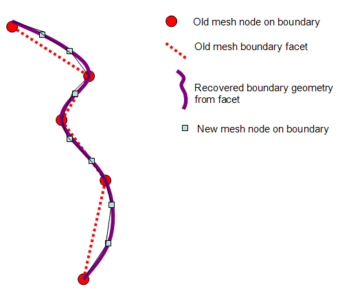
The new mesh is acceptable even if the smoothed boundary geometry of the new mesh does not correspond exactly to the faceted geometry of the old mesh, as shown in Figure 7.4: Boundary Geometry of a Generic (CDB) New Mesh; however, the offset must be very small.
In a 3D analysis involving contact, the difference of the recovered boundary geometry from the faceted boundary of the old mesh affects mapping results much more so than in a 2D analysis. Accurate geometry extraction is therefore essential in 3D rezoning.
If the rezoned part has contact/target elements, the program generates those elements automatically for the new mesh, depending on whether the underlying old mesh had the same type of contact/target elements. Isolated rigid target elements in the model remain the same throughout the analysis and cannot be remeshed; however, all contact and target elements associated with solid elements are candidates for remeshing. While it is possible to read in the new contact/target elements of the new mesh from the .cdb file, it is faster and more reliable to read in only the remeshed solid elements and allow the program to generate the new contact/target elements.
The .cdb file of the new mesh must have no line
breaks in the NBLOCK and EBLOCK records. Also, while
writing the mesh .cdb file, a block file format is
necessary (CDWRITE,,,,,,,Fmat,
where Fmat = BLOCKED).
The REMESH command's REGE option regenerates all node and element numbers on the new mesh using an offset of the highest existing node and element numbers. The KEEP option keeps the similarly numbered nodes and elements in the new and the old meshes unchanged.
Apply Option = KEEP carefully. It assumes that
either the new mesh node and element numbers are already offset by the
maximum node and element number of the old mesh or that the common node and element numbers in the new mesh
and the old mesh match geometrically.
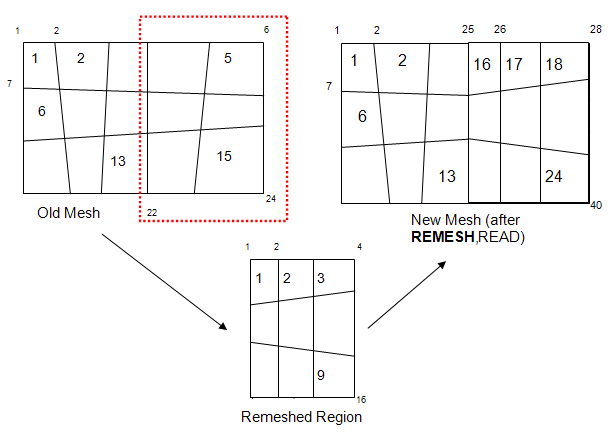
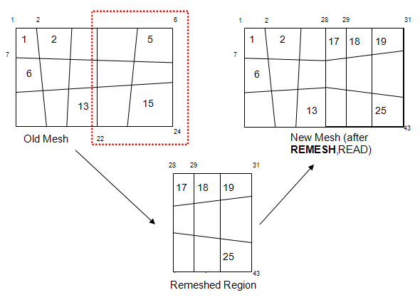
The following figure illustrates how the REMESH command's REGE and KEEP options work:
Figure 7.5: Remeshing Options when Using a Generic (CDB) New Mesh
In this example, a meshed domain with 24 nodes and 15 elements is remeshed using the REMESH command's REGE (default) option. The .cdb file for the new mesh has nodes 1 through 16 and element numbers 1 through 9. After remeshing, these node and element numbers are suitably offset by the maximum node and element numbers (that is, 15 and 24, respectively) of the old mesh.
The same problem appears in this example. However, the .cdb file for the new mesh has node numbers defined from 28 through 43 and element numbers defined from 17 through 25. In this case, remeshing occurs using the REMESH command's KEEP option, so the node and element numbers are not offset.
For more information, see the REMESH command documentation as it applies to remeshing using a generic mesh created by another application.
You can manually split an existing mesh to obtain the solution of a nonlinear analysis which cannot otherwise converge, or to improve its accuracy.
Mesh splitting increases the number of degrees of freedom of the model by enriching the existing mesh. It is a useful option for rezoning if the number of degrees of freedom must be increased in contact gaps, or if a new program-generated mesh or generic third-party mesh does not fully satisfy your requirements.
As shown in Figure 7.3: Rezoning Using Manual Splitting of an Existing Mesh, the mesh-splitting remeshing method requires the REMESH,SPLIT command, used in place of commands required for other meshing methods.
Elements that have had midside nodes added or dropped (EMID) cannot be split.
The following topics about manual mesh-splitting are available:
- 7.7.1.3.1. Understanding Mesh Splitting
- 7.7.1.3.2. Geometry Details for Mesh Splitting
- 7.7.1.3.3. Using the REMESH Command for Mesh Splitting
- 7.7.1.3.4. Mesh-Transition Options for 2D Mesh Splitting
- 7.7.1.3.5. Mesh-Transition Options for 3D Mesh Splitting
- 7.7.1.3.6. Improving the Local Topology of Tetrahedral Meshes via Edge and Face Swapping
- 7.7.1.3.7. Improving Tetrahedral Element Quality via Mesh Morphing
Splitting occurs on selected solid elements in the mesh. If no solid elements are explicitly selected, the program splits all solid elements in the mesh. The mesh-splitting capability generally applies to remeshing cases in mesh-rezoning problems using the elements listed in Rezoning Requirements and Limitations.
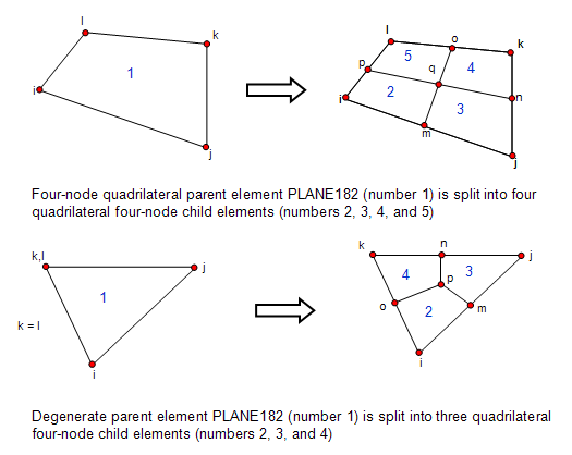
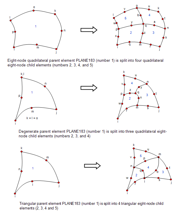
The program splits parent elements into child elements, as follows:
A parent quadrilateral element into four child quadrilateral elements
A parent 2D degenerate element into three child quadrilateral elements
A parent triangular element into four child triangular elements
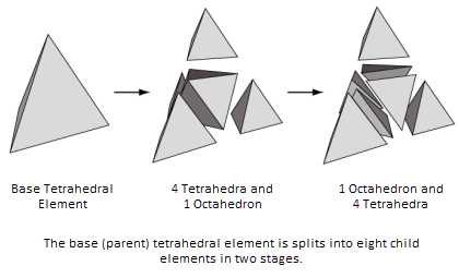
A parent tetrahedral element into eight child tetrahedral elements
For more information, see Geometry Details for Mesh Splitting .
Child elements inherit all shape characteristics of the parent element. Therefore, if a particular element is badly distorted and is causing convergence difficulties, simply subdividing the element by splitting it does not improve convergence.
The REMESH command's SPLIT option uses no geometry information; instead, it uses only information about the mesh itself (that is, nodal connectivity and nodal coordinates).
All child elements automatically inherit all attributes of the parent element from which they were generated. Quadrilateral parent elements are split into four child elements, 2D degenerate parent elements are split into three quadrilateral child elements, and triangular parent elements are split into four triangular child elements, as shown in the following figures:
To perform mesh-splitting, select the region to be rezoned (via the GUI or the ESEL command). After you have selected the target region, issue a REMESH,SPLIT command.
You can issue multiple REMESH,SPLIT commands for various parts of the mesh in the same rezoning problem (referred to as horizontal rezoning). These multiple zones can overlap or they can be isolated; however, a large number of overlaps can cause badly shaped transition elements to develop.
If the rezoned part has contact/target elements, the program generates those elements automatically for the new mesh (according to whether the underlying old mesh had the same type of contact/target elements). Isolated rigid target elements in the model remain the same throughout the analysis and cannot be remeshed; however, all contact and target elements associated with solid elements are candidates for remeshing. When you split a solid element that is associated to contact/target elements, the program deletes these associated contact/target elements. The program generates the correct contact/target elements for the new child elements automatically at the end of the remeshing operation (REMESH,FINISH).
Because splitting refinement is mesh-based and not geometry-based, it
cannot be undone after it has occurred. To create a different or new
splitting scheme, or to revert to the original mesh, you must create a new
rezoning environment
(REZONE,MANUAL,LDSTEP,SBSTEP).
For more information about using the REMESH,SPLIT command, see Mesh-Transition Options for 2D Mesh Splitting and Mesh-Transition Options for 3D Mesh Splitting.
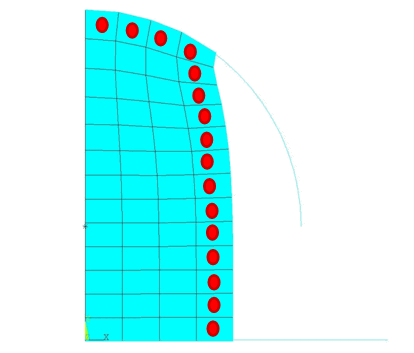
The default REMESH,SPLIT command forces the transition elements to be mostly quadrilateral and minimizes the number of degenerated elements. The command can also be issued as:
REMESH,SPLIT,,,TRAN,QUAD
Issuing the REMESH command using the transition and quadrilateral options helps with convergence because non-degenerate elements are less prone to locking behavior.
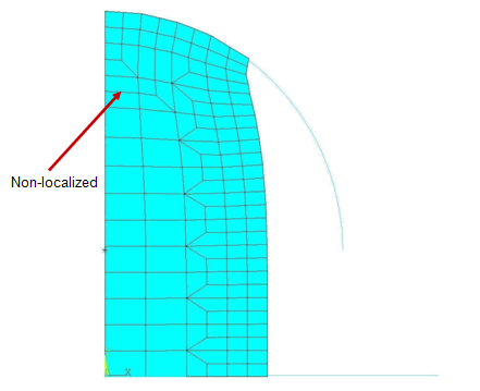
It is possible that transition elements designed in such a way can disturb the localization of the mesh. The element subdivision that occurs when transitioning from the split zone can traverse several element layers.
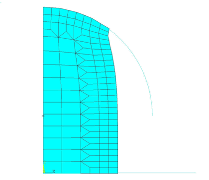
The following figure illustrates the options for transition element generation:
Splitting with single-layer transition and degenerate elements.
In this case, the REMESH,SPLIT,,,TRAN,DEGE command applies.
Unlike in 2D splitting, command-driven transition element control is not supported in 3D splitting. The program generates the transitions automatically.
For tetrahedral meshes, transitions are generated for horizontal rezoning and partial remeshing.
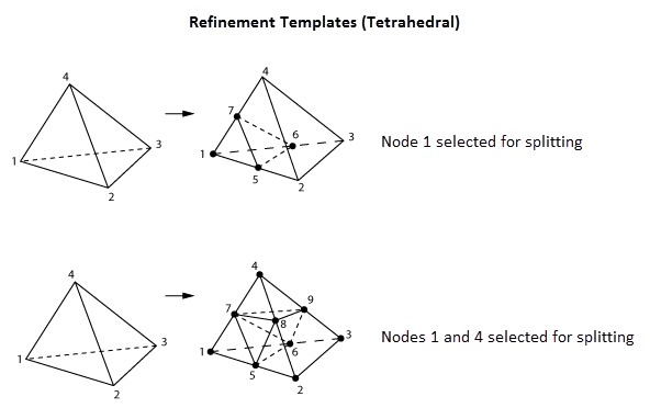
For any tetrahedral element, if all four or any three nodes are selected by the program as candidates for splitting, the entire element is split into eight child tetrahedra (as shown in Figure 7.8: Splitting Tetrahedral Linear Elements (SOLID285))). However, different transition element schemes are developed for cases when only one or two nodes in a tetrahedron are selected for splitting.
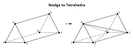
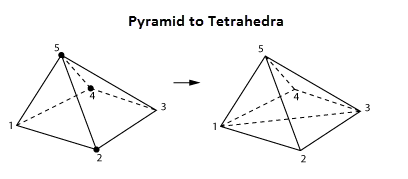
The transition process is a two-phase operation: the first phase usually creates one or more tetrahedral elements and pyramids and /or prisms (depending on the splitting template), and the second phase further decomposes the pyramids and/or prisms into child tetrahedra.
The following figure shows the first phase of the transitions for parent tetrahedra when one and two nodes are selected for splitting:
In the first case, the selected node is 1. From the parent tetrahedron (1-2-3-4), one child tetrahedron (1-5-6-7) and one child prism (5-6-7-2-3-4) are created. In the second case, nodes 1 and 4 are selected for splitting, creating two child tetrahedra (1-5-6-7 and 4-8-9-4), one child pyramid (5-8-9-6-7), and one child prism (2-5-8-3-9-6).
In the second phase of transition creation, the prisms and pyramids are further split into tetrahedra, as shown in the following two figures:
The prism (1-2-6-4-3-5) is split into three tetrahedra (1-2-6-4, 2-4-3-6, and 3-4-5-6). No new nodes are created. The diagonals are created to maintain compatibility with the neighboring elements and are selected on the basis of best element shape metrics of the child elements.
The pyramid (1-2-3-4-5) is split into tetrahedra (1-2-3-5 and 1-3-4-5). No new nodes are created. The diagonal is created to maintain compatibility with the neighboring elements and are selected on the basis of best element shape metrics of the child elements.
Splitting a mesh ensures that child elements inherit all properties from parent elements. For 3D splitting, a deformed parent tetrahedral element produces eight distorted child tetrahedra. If high deformation exists at the solution substep at which splitting occurs, the mapping operation (MAPSOLVE) may not converge. It is also possible that the solution may not proceed much further after the analysis restart, as the child elements themselves are distorted.
To improve tetrahedral element quality, the program modifies the local topography of the elements automatically when the REMESH,SPLIT command executes. The modifications use edge- and face-swap operators to change the connectivity of a group of contiguous tetrahedral elements to improve the shape metrics of the elements.
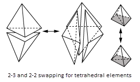
The swap operations are usually referred to as i-j swapping, where i is the number of tetrahedrons before swapping and j is the number of tetrahedrons after swapping. Support is available for 2-2, 2-3, 3-2, and 4-4 swaps.
The following figure shows an example of 2-3 and 2-2 swapping:
In addition to swapping, the program also performs mesh morphing to improve tetrahedral element quality after splitting occurs. As with swapping, morphing occurs automatically on the split elements when the REMESH,SPLIT command executes.
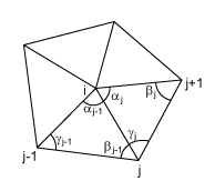
The mesh-morphing operation maintains the mesh connectivity but moves the nodes to improve element shape metrics. The operation uses the following cotangent-weighted Laplacian operator to perform an iterative node-wise morphing:
where:
| L(v) = Node movement vector |
| N = Number of elements adjacent to patch node i |
| V = Position vector of node |
| W = Weight function (given by |
The weight function is based on the cotangent of the face angles of the tetrahedral elements sharing the node i, shown in the following figure:
The mesh-morphing process stops when the node movement no longer improves shape metrics or the magnitude of the node movement becomes negligibly small.
Creating a better mesh is the key to successful rezoning. The new mesh must be better than the old mesh; otherwise, rezoning cannot improve convergence, and can even result in nonconvergence if the new mesh is worse.
Generally, a good mesh has these characteristics:
The element internal angles do not approach 180 degrees or 0 degrees.
The opposite edges or faces of quadrilaterals have less cross angle (that is, they are closer to parallel with each other).
Boundary nodes are more evenly distributed.
The elements have a better aspect ratio.
For creating a good mesh, satisfactory internal angles are a more important consideration than whether aspect ratios may be too high or too low. For 2D meshes, avoid triangle elements as much as possible; however, if quadrilateral elements have very large internal angles, it is preferable to accept some triangle elements with more acceptable internal angles instead.
The quality of the new mesh is fully dependent on the shape of the selected region, neighboring elements, and boundary nodes with applied loads and boundary conditions. It may sometimes be necessary to edit or modify the new mesh prior to the mapping operation (MAPSOLVE); in such cases, several preprocessing (/PREP7) commands are available to help you create a good mesh on the selected region:
Figure 7.15: /PREP7 Mesh-Control Commands Available in Rezoning
| Type of Mesh Control Desired | Applicable Commands |
|---|---|
| Element size | AESIZE, DESIZE, ESIZE, KESIZE, LESIZE, and SMRTSIZE |
| Element shape | MOPT, MSHAPE, and MSHKEY |
| Element internal angles | SHPP,MODIFY to reset the shape parameter limits. Specify input values of 11~14 and 17~18 depending on the element type. |
| Boundary node distribution | Boundary nodes require special attention. Use the LESIZE command to space the nodes as uniformly as possible without disturbing other characteristics of the mesh. |
| Refining | AREFINE, EREFINE, KREFINE, LREFINE, NREFINE, |
| Other |
ACLEAR, AMESH, KSCON, LCCALC, MSHMID If you remesh using a generic new mesh (rather than a program-generated mesh), the N and EN commands are also available. The ACLEAR command applies only to the area generated via the AREMESH command (that is, when remeshing using a program-generated new mesh). |
The mesh-control commands are available at any point after issuing a REMESH,START command and before issuing a REMESH,FINISH command.
Nodes at which force or isolated displacements are applied must remain during remeshing, as do nodes at the boundaries of distributed displacements, pressures, or contact/target surfaces. The new elements must have the same attributes as the old elements, such as element type, material, real constant, and element coordinate system. The program rotates the new nodes to the same angles as the old nodes in the region or on the boundary, as the case may be.
After creating the new mesh, verify that the new elements cover the entire selected region and are compatible with neighboring regions. (If another region requires remeshing, you can do so, but do not issue another REMESH,START command.
You can create a new mesh for more than one region in the same deformed domain. Remeshing two or more regions at the same specified substep is called horizontal rezoning.
Use horizontal rezoning if you intend to remesh:
Two regions with different materials, element coordinate systems, nodal coordinate systems, or real constants
The elements on both sides of a contact boundary
Two groups of highly distorted, noncontiguous elements
Horizontal rezoning using a program-generated new mesh or a generic new mesh is possible only when the remeshed areas are isolated from each other or, at most, share an interface; however, the remeshed areas may not intersect. This restriction does not exist for manual mesh splitting.


