The following example simulations introduce you to rezoning:
Also see these example problems that use rezoning in the Technology Showcase: Example Problems:
Following is an example simulation involving a sealing assembly problem. The example uses a program-generated new mesh for the remeshing operation.
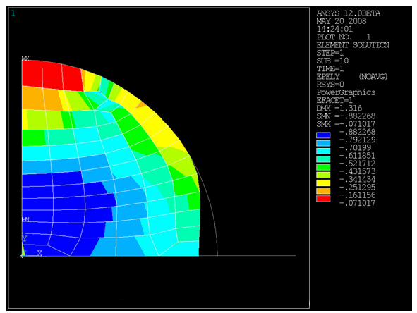
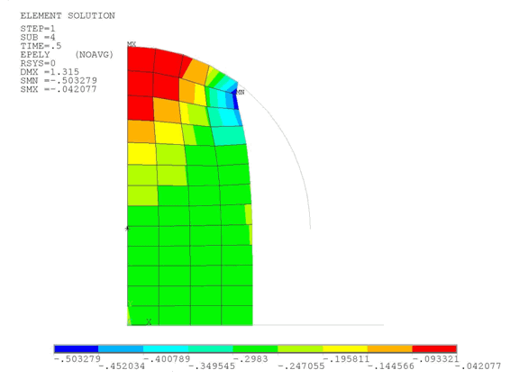
A rubber seal has an initial rectangular shape and consists of a hyperelastic material modeled with two parameters as a Mooney-Rivlin model. A shaft has a circular cross section and is assumed to be rigid. The shaft moves down vertically. The simulation plots the element strain in the y direction.
Given the initial input, the simulation terminates at substep 10 (TIME = 0.44) because of a mesh distortion. After rezoning, which occurs at substep 7, the simulation concludes successfully with the new mesh.
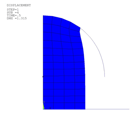
This input results in a deformed mesh and causes the analysis to terminate:
/batch,list
/filname,RznExample1

/prep7

/com define parameters
h=20
b=10
el=b/8
xc=17.5
yc=32.99038
rc=15
PilotMove= -13

c10=62.3584129
c01=-37.8485452
dd=1e-4

/com define element types, material, etc.
et,1,182
keyopt,1,3,2
keyopt,1,6,1

et,2,169
et,3,172
keyopt,3,9,0
keyopt,3,10,0

et,4,169
et,5,172
keyopt,5,9,0
keyopt,5,10,0

tb,hyper,1,,2,mooney
tbdata,1,c10,c01,dd

mp,mu,2,0.0

r,3
r,4

/com define geometry
k,1,xc,yc
k,2,xc,yc,yc
k,3,xc-rc,yc
k,4,0.0,0.0
k,5,2*rc,0.0
rect,0,b,0,h
circle,1,rc,2,3,360,1
/pnum,line,1
lplot
l,4,5
lplot
aplot

/com create solid elements
esize,el
mat,1
type,1
real,1
amesh,1

/com generate the 1st contact pair
mat,2
real,3
type,2

esize,h
lmesh,5,7
*get,PilotID,node,,num,max
PilotID=PilotID+1
nkpt,PilotID,1
tshap, pilo
e,PilotID

type,3
lsel,,,,2,3
nsll,,1
esln,,0
esurf
alls

/com generate the 2nd contact pair
real,4
type,4

lmesh,8
lsel,,,,8
esll
esurf,,reverse
alls

type,5
lsel,,,,1,2
nsll,,1
esln,,0
esurf
alls

/com apply boundary conditions and loads
d,PilotID,ux,0.0
d,PilotID,uy,PilotMove
d,PilotID,rotz,0.0

lsel,,,,4
nsll,,1
d,all,ux,0.0
alls

lsel,,,,8
nsll,,1
d,all,uy,0.0
alls

nlist
elist
dlist

/com check the contact definition
cncheck
finish

/solution
rescontrol,,all,1
pred,off
nlgeom,on
time,1
NSUBST,10,100,5
outres,all,all
solve
finish

/post1
set,1,6
prns,u,comp
prns,s,comp
prns, cont
finish
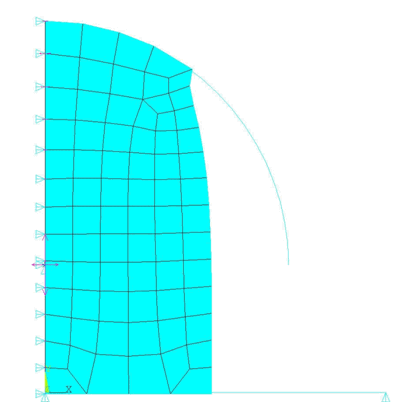
This input uses rezoning to remesh the deformed region and allow the analysis to proceed using the new mesh:
/batch,list
/clear,nostart
/filname,RznExample1

/solution

rezone,manual,1,6  ! specify the substep to rezone

remesh,start       ! start remeshing operation
esel,,,,65,128     ! select region to remesh
aremesh            ! create area for new mesh
lesize,10,,,8
lesize,31,,,10
lesize,18,,,6
amesh,2            ! create the new mesh
esel,all
nsel,all
remesh,fini        ! finish remeshing operation

elist              ! check the new model, BC and loads
dlist

mapsolve,50        ! map solutions

finish

/solution          ! restart
antype,,restart
solve
finish
Following is an example simulation involving a heading assembly problem. The example uses an imported generic mesh generated by another application for the remeshing operation.
The model represents an axisymmetric hollow hemisphere that pushes down a cylindrical workpiece. The spherical ball and the grip die are modeled as rigid surfaces. Due to element distortion, the initial run stops at t = 0.7875. Rezoning is applied at this time to achieve complete loading. The entire deformed model at substep 4 is imported into Ansys ICEM CFD, which generates a new mesh. After reading the new mesh back in, the program creates the contact automatically when you issue the REMESH,FINISH command.
The solid element used in the model is PLANE182 (using the B-Bar method with mixed u-P formulation). CONTA172 and TARGE169 elements are also used. The material model used is a hyperelastic material with a three-parameter OGDEN option.
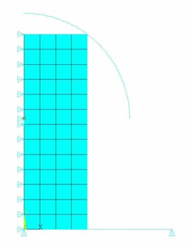
This is the initial mesh:
This input results in a deformed mesh and causes the analysis to terminate at t = 0.7875 seconds:
/batch, list
/filname,RznExample2
/prep7
h=4.6295
b=1.5
el=b/4
xc=0
yc=2.6295
rc=2.5
PilotMove= -yc
! ogden parameters
TB,HYPE,1,1,3,OGDE
TBTEMP,0
TBDATA,1,3.2084E-009,7.281,0.035198,3.0149,6.3712,2.0493
et,1,182
keyopt,1,3,0
keyopt,1,6,1
et,2,169
et,3,172
keyopt,3,9,0
keyopt,3,10,0
et,4,169
et,5,172
keyopt,5,9,0
keyopt,5,10,0
mp,mu,2,0.0
r,3
r,4
k,1,xc,yc
k,2,xc,yc,yc
k,3,rc,yc
k,4,0.0,0.0
k,5,rc+1,0.0
rect,0,b,0,h
circle,1,rc,2,3,90,1
/pnum,line,1
lplot
l,4,5
lplot
aplot
esize,el
mat,1
type,1
real,1
amesh,1
/pnum,elem,1
/pnum,node,1
/com the 1st contact pair
mat,2
real,3
type,2
esize,h
lmesh,5
lsel,,,,5
esll
esurf,,reverse
alls
*get,PilotID,node,,num,max
PilotID=PilotID+1
nkpt,PilotID,1
tshap, pilo
e,PilotID
type,3
lsel,,,,2,3
nsll,,1
esln,,0
esurf
alls
/com the 2nd contact pair
real,4
type,4
lmesh,6
lsel,,,,6
esll
esurf,,reverse
alls
type,5
lsel,,,,1,2
nsll,,1
esln,,0
esurf
alls
d,PilotID,ux,0.0
d,PilotID,uy,PilotMove
d,PilotID,rotz,0.0
lsel,,,,4
nsll,,1
d,all,ux,0.0
alls
lsel,,,,6
nsll,,1
d,all,uy,0.0
alls
/solution
pred,off
rescontrol,,all,1,
eresx,no
nlgeom,on
time,1
NSUBST,10,100,5
outres,all,all
solve
finish
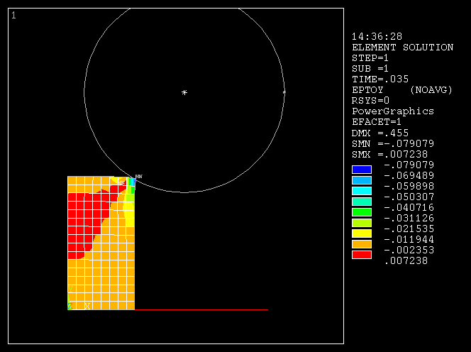
Following is the total elastic strain along the Y axis at t = 0.7875. The element distortion is apparent and causes the problem to diverge.
When the nonlinear analysis stops, reload the database at load step 1 and substep 4. Select all solid elements and write out to a .cdb file. (Only solid elements can be read in later when you are ready to generate the new mesh.)
/clear,nostart
/filname,RznExample2
/solu									! enter solution environment
rezone,manual,1,4					! start rezoning at load step1, substep 4
eplot									! plot the elements
etlist									! list the element types
ESEL,S,TYPE,,1						! select only the elements of type ‘1’(solids)
cdwrite,db,RznExample2,cdb	! write out the selected elements to a CDB file
finish
With the deformed mesh corresponding to load step 1, substep 4 is shown next. Ansys ICEM CFD uses the boundary segments of this mesh next to generate the new mesh. The nodal discretization at the boundary remains same for both the old and the new mesh.
Next, the total elastic strain along the Y axis for this mesh is shown. This is one of the state variables which is transferred to the new mesh when mapping solved node and element solutions from the original mesh to the new mesh (MAPSOLVE).
At this stage of the rezoning process, start Ansys ICEM CFD and read in the .cdb file. (Reminder: As indicated in Exporting the Distorted Mesh as a CDB File, only solid elements can be read in.)
Generate the new .cdb file as follows:
Import the .cdb file in Ansys ICEM CFD as mesh ().
Extract triangulated (STL) geometry from the mesh ()
Set the global maximum element size in the order of the element size that you require ().
Build the topology ()
Select the "Respect line elements" and "Protect given line elements" options ().
Compute the new mesh ().
Select the tab and write the input file. Do not include the bar elements.
Rename the new input file as a .cdb file.
The new mesh obtained from Ansys ICEM CFD is shown here. Notice that the boundary discretization remains the same as that of the old mesh.
Continue rezoning with the new mesh (.cdb file) and restart the analysis, as follows:
/clear,nostart
/filname,RznExample2
/solu												! enter solution environment
rezone,manual,1,4								! start rezoning from load step 1, substep 4
remesh,start										! start remeshing
remesh,read,RznExample2,cdb,rege		! read in the new mesh (CDB file)
remesh,finish									! finish remeshing, autogenerate contacts
mapsolve,500,pause							! do state variable mapping and equilibriation
finish
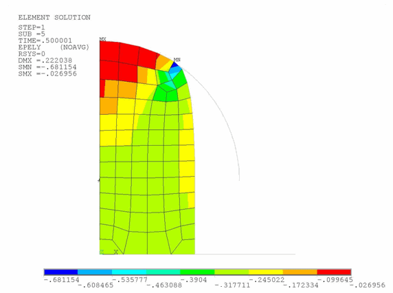
After the MAPSOLVE command has executed (mapping the solved node and element solutions from the original mesh to the new mesh), the total elastic strains along Y for the new mesh appears. Notice that some expected nodal realignment has occurred in the new mesh.
Restart the problem. The solution to progresses to t = 1s.
/clear,nostart
/filname,RznExample2
/solu							! enter solution environment
antype,,restart			! multiframe restart
solve							! solve the problem
finish
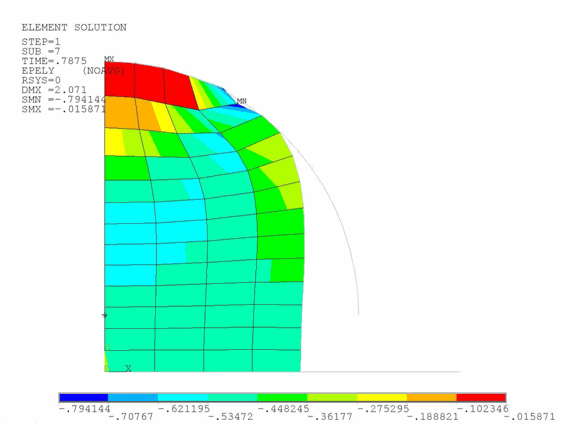
Allow the analysis to complete. Following is a plot of the total elastic strain along the Y direction: