The rezoning process involves the following general steps:
Determine the load step and substep at which the region must be remeshed.
Initiate the rezoning process.
Select the region to remesh.
Remesh the region with a mesh of better quality than the distorted mesh in the original domain.
Verify boundary conditions, loads, temperatures, and fluid-penetration parameters applied to the new mesh (from the old, distorted mesh).
Automatically map displacements and state variables from the old (distorted) mesh to the new mesh and rebalance the resulting residual forces.
Use the restart capability to continue the analysis.
You can select one or more parts, or regions, of the mesh to repair at the same time. You can also perform rezoning multiple times in an analysis.
The following topics about the general rezoning process are also available:
The following flowcharts illustrate the general rezoning process according to the remeshing method used:
Some mesh-generation methods are limited to 2D analyses only.
For information about the commands shown in the flowcharts, see Key Commands Used in Rezoning or the documentation for a given command in the Command Reference.
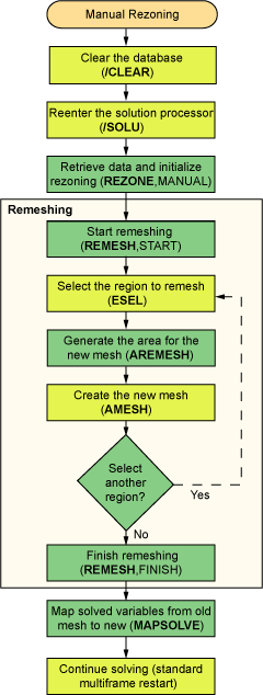
Figure 7.1: Rezoning Using a Program-Generated New Mesh
This flowchart shows a process for 2D rezoning using a new mesh generated internally by the program (AREMESH and AMESH):

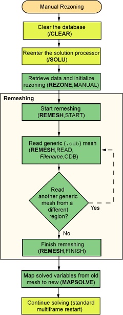
Figure 7.2: Rezoning Using a Generic New Mesh Generated by Another Application
This flowchart shows a process for both 2D and 3D rezoning using a generic (.cdb format) new mesh generated by a third-party application:

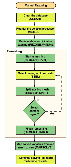
Figure 7.3: Rezoning Using Manual Splitting of an Existing Mesh
This flowchart shows a process for 2D rezoning by splitting an existing mesh:

For 3D mesh splitting, command-driven transition element control (ESEL) is not used. The program generates the transitions automatically.
Following is a description of key commands used in the rezoning process and provides supplemental information to the rezoning process flowcharts.
| Command | Description | Rezoning Comments |
|---|---|---|
| /CLEAR | Clears the database | Always clear the database first, before reentering the solution processor (/SOLU) and starting the rezoning process. |
| REZONE | Initiates rezoning | When you initiate rezoning, the program verifies that the
necessary files (.rdb,
.rst,
.rnnn
, and .ldhi) exist for the specified
substep and rebuilds the data environment at that substep. All nodes are updated to the deformed geometry in preparation for remeshing. |
| REMESH | Generates or obtains the new mesh required for rezoning | You can remesh more than
one region
at the same specified substep
during the rezoning process. After remeshing (REMESH,FINISH), the program generates contact elements (if any) and transfers loads and boundary conditions automatically. For more information, see Step 4: Perform the Remeshing Operation. |
| MAPSOLVE | Maps node and element solutions | After remeshing, this command maps the solved nodal and element solutions from the original (distorted) mesh to the new mesh and achieves equilibrium on the new mesh. |


