The following examples are available:
This section describes a sample static edge-based analysis employing SOLID236 3D 20-Node Electromagnetic Solid elements
This example examines the solution in the slot of an electric machine. For a specified current, the analysis calculates the magnetic field, energy, Joule heat losses, and Lorentz forces.
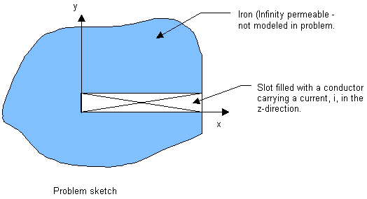
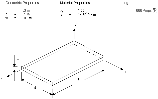
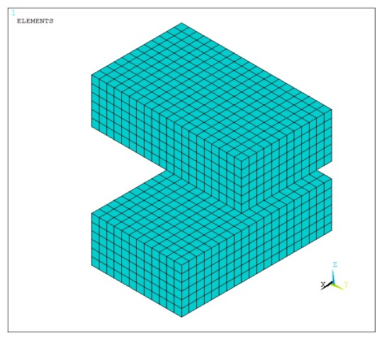
Figure 6.4: Current-Carrying Conductor in a Slot Within an Iron Region and Figure 6.5: Volume Model of the Conductor below illustrate, respectively, the problem domain and a volume model of the conductor within the slot in the domain.
The geometry is a block modeling a slot of an electrical machine. The Z-axis coincides with the axis of the machine; l = 0.3 m is the length. The slot, with a depth of d = 0.1 m, is oriented in the X-axis. The width of the slot in the y direction is denoted by w = 0.01 m. A conductor with relative permeability, μr = 1, and resistivity, ρ = 1.0e-8, carries a current, I=1000 A, in the Z direction.
The side and bottom of the slot are ideal iron. This is a flux-normal boundary condition (natural, or Neumann, boundary condition); it is satisfied automatically without any prescription of an explicit boundary condition.
At the opening of the slot at X = d and at axial faces Z = 0 and Z = 1, the flux lines are parallel. This is an essential flux-parallel (Dirichlet) boundary condition; that is, its satisfaction is not automatic. You can prescribe it by constraining the flux-edge DOFs – AZ - to zero.
The example uses MKS units (the default).
| l = 0.3 | Length |
| d = 0.1 | Depth |
| w = 0.01 | Width |
| I = 1000 | Current |
| μr = 1 | Relative magnetic permeability |
| ρ = 1.0e-8 | Electric resistivity (required for Joule heat loss) |
| n = 5 | Number of divisions through the slot depth |
Target data for the example are as follows:
| Vt = d w l | = 3e-4 | m^3 - volume |
| Hy = i/w x/d | = 1e5 x/d | A/m - magnetic field |
| By = mur mu0 H | = 4e-2 π x/d | T - flux density |
| Jz = i/ (d w) | = 1e6 | A/m^2 - current density |
| JLOSS | = 3.00 | W |
| Fx = -integral Jz By dV | = -18.85 | N - total force |
| SENE | = .622 | J - energy |
/ Analysis of a Current-Carrying Conductor
/nopr

! *** Problem parameters
l=0.3                ! length
d=0.1                ! depth
w=0.01               ! width
I=1000               ! current
mur=1                ! relative magnetic permeability
rho=1.0e-8           ! electric resistivity (required for Joule heat loss)
n=5                  ! number of divisions through the slot depth

! *** Derived parameters
jx=0                 ! current density; x, y, z refer to component
jy=0
jz=I/d/w

! *** Expected results
/com,
/com, Hy = I/w*X/d = 1e5X/d A/m
/com, By = mur*mu0*H = 4e-2*Pi*X/d T
/com, Jz = I/(d*w) = 1e6 A/m^2
/com, JHEATloss = 3.0 W
/com, Fx = -integral (Jz*By*dV) = -18.85 N
/com, Energy = 0.622 J
/com,

! *** Create Model
/prep7
et,1,236             ! define magnetic element type - SOLID236
keyopt,1,8,1         ! use Lorentz force option
mp,murx,1,mur        ! define relative permeability
mp,rsvx,1,rho        ! define electric resistivity

block,0,d,0,w,0,l    ! define rectangular block volume region

lsel,s,loc,X,d/2     ! select lines to specify the number of elements
lesize,all,,,n       ! divide the lines along the slot depth for meshing
lsel,all             ! select all lines
esize,,1             ! solid volume are subdivided into elements
vmesh,all            ! mesh solid volumes
fini

/solu
! *** Apply Flux-parallel boundary condition
asel,s,loc,X,d       ! select areas at the opening of the slot, x=d
asel,a,loc,Z,0       ! add areas at Z=0 to the selected set
asel,a,loc,Z,l       ! add areas at Z=l to the selected set
da,all,az,0          ! apply a zero constraint on selected areas to specify a
                     ! flux-parallel condition
asel,all             ! select all areas.

! *** Prescribe current density - body load
bfe,all,js,,jx,jy,jz ! apply current density on all selected elements

solve
fini

! *** Extract solution
/post1
presol,h             ! print magnetic field at the corner nodes of elements
/com
presol,b             ! print flux density at the corner nodes of elements
/com
presol,jt            ! print current density at element centroids
/com
presol,jheat         ! print Joule heat per volume in elements
/com
presol,fmag          ! print magnetic force at the corner nodes of elements

EMFT                 ! sum up forces

/view,1,1,.4,.5      ! change the viewing angle for displays
/com
plnsol,h,sum         ! plot the H field; data from the elements are averaged
/com
plnsol,b,sum         ! display the flux density, B (magnitude)
/com
plvect,h,,,,vect,node,on  ! display as a vector the field intensity H

/com
! *** store element output items
etable,fe,fmag,X     ! x-component of FMAG force
etable,hy,h,y        ! y-component of the magnetic field
etable,by,b,y        ! y-component of the flux density
etable,jz,jt,z       ! z-component of the current density
etable,pd,jheat      ! Joule heat rate per unit volume
etable,ve,volu       ! element volume
etable,we,sene       ! element magnetic energy (SENE)
smult,pe,pd,ve       ! element Joule heat

! *** Print the element table items
pretab,ve,by,hy,we
pretab,ve,jz,jh,pe
pretab,ve,jz,by,fe

ssum                 ! sum the entries in the element table

! *** Obtain (*get) the results of the summation (ssum)
*get,ft,ssum,,item,fe
*get,wt,ssum,,item,we
*get,pt,ssum,,item,pe
*get,vt,ssum,,item,ve

*VWRITE,vt,ft,wt,pt
(/'volume=',e10.3,' force=',e10.3,' energy=',e10.3,' loss=',e10.3/)
fini

! *** couple with thermal analysis
/prep7               ! enter preprocessor
et,1,90              ! change element type to thermal
ldread,hgen,,,,,,rmg ! read heat generation load from the result file
bfelist,all,hgen     ! list heat generation element body loads
fini

! *** couple with structural analysis
/prep7
et,1,186             ! change element type to structural
ldread,forc,,,,,,rmg ! read nodal-force load from the result file
flist                ! list nodal forces
fini
This example problem considers the magnetic force interaction between two permanent magnets. The magnet configuration and the analytical solution are described in "3D Analytical Calculation of the Forces Exerted between Two Cuboidal Magnets" by G. Akoun and J.-P. Yonnet, IEEE Transactions on Magnetics, vol. MAG-20, No. 5, pp. 1962-1964 (1984)
Two permanent magnets of sizes 20 x 12 x 6 mm and 12 x 20 x 6 mm are positioned in space such that their respective sides are parallel and their centers are offset by -4 mm in the X- and Y-directions and by 8mm in the Z-direction with respect to the lower magnet (Figure 6.6: Finite Element Model of the Magnets). In both magnets, the residual induction vector of magnitude 0.38 tesla is oriented along the Z-axis.
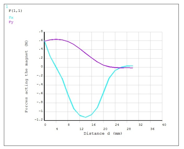
A series of magnetostatic analyses is performed to determine the magnetic forces Fx and Fy acting on the magnets as the upper magnet moves in the X-direction (Figure 6.7: Magnetic Forces vs. Upper Magnet Displacement). The magnets are enclosed in an air box of size 60 x 60 x 54 mm. Flux parallel boundary conditions are imposed on the exterior surface of the air enclosure. Both the magnets and the air region are modeled using the magnetic analysis option (KEYOPT(1)=0) of SOLID236. For a more accurate force summation over the regions with corners, the midside nodes contribution to magnetic forces is included in the corner node FMAG force output (KEYOPT(7)=1).
The EMFT command macro is used to sum up the element FMAG forces acting on the lower magnet (volume 2). Note that to correctly sum up the Maxwell forces using the EMFT macro, you must select all the nodes of the lower magnet as well as the elements attached to those nodes.
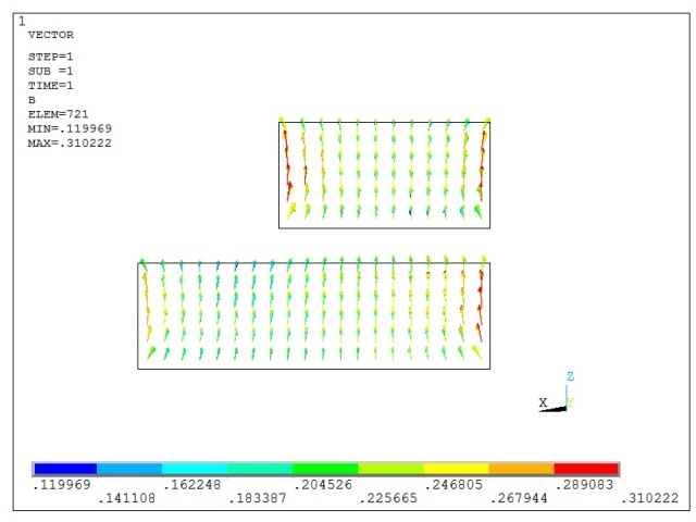
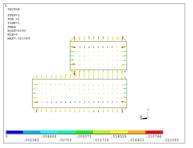
The side view of the magnetic field and magnetic force distribution for the initial position of the upper magnet (d = 0 mm) are shown in Figure 6.8: Magnetic Field Distribution in the Magnets and Figure 6.9: Magnetic Force Distribution in the Magnets respectively.
/title, Forces between two permanent magnets
/nopr

!npts=16
!*dim,dist,table,npts
!*dim,F,table,npts,2
d=0
d_air=0

!*do,i,1,npts

!parsave,all
!/clear,nostart
!parres

! Problem parameters
Pi=acos(-1)
mu0=4*Pi*1e-7                     ! permeability of free space, H/m
mu0r=1                            ! relative permeability of free space
Br=0.38                           ! residual induction, tesla
a=10 $ b=6 $ c=3                  ! lower magnet dimensions
aa=6 $ bb=10 $ cc=3               ! upper magnet dimensions
xo=-4 $ yo=-4 $ zo=8              ! upper magnet center offset

/com, *** Upper Magnet Displacement d = %d% (mm)

/PREP7
! Solid model
block,-a,a,-b,b,-c,c              ! lower magnet volume
wpoff,xo,yo,zo
block,-aa+d,aa+d,-bb,bb,-cc,cc    ! upper (moving) magnet volume
vplot
wpoff,-xo,-yo,-zo
block,-30,30+d_air,-34,26,-23,31  ! air box
vovlap,all

! Finite element model
esize,1
et,1,SOLID236                     ! magnetic solid
keyop,1,7,1                       ! condense forces to the corner nodes
vmesh,1,2
esize,4
numcmp,volu
msha,1,3D
vmesh,3

! Material properties
mp,mgzz,2,Br/mu0
mp,murx,2,mu0r
mp,murx,1,mu0r
vsel,s,,,1,2,,1
emod,all,mat,2
alls

nsel,s,ext
d,all,az,0                        ! flux parallel boundary conditions
alls

vlscale,all,,,1e-3,1e-3,1e-3,,,1  ! scale the volumes to mm

WPSTYLE,,,,,,,,0
/ANG,1
/VIEW,1,1,1,1
/VUP,1,Z
esel,s,mat,,2
eplot
alls
fini

/SOLU
solve
fini

/POST1
vsel,s,,,2,,,1                    ! select lower magnet along with the
                                  ! associated elements and nodes
esln
EMFT                              ! sum up magnetic forces
alls

esel,s,mat,,2
/VSCALE,,0.3
plvect,b,,,,vect,elem,on,on       ! plot magnetic field
plvect,fmag,,,,vect,node,on,on    ! plot magnetic forces
alls
fini

!/com, i = %i%
!dist(i)=d
!F(i,1)=_fxsum                    ! FX sum calculated by EMFT
!F(i,2)=_fysum                    ! FY sum calculated by EMFT
!d=d+2                            ! upper magnet displacement update
!*if,d,gt,8,then
!d_air=d-8
!*endif
!*enddo

!/axlab,x,Distance d (mm)
!/axlab,y,Forces acting the magnet (N)
!/gcol,1,Fx
!/gcol,2,Fy
!*vplot,dist(1),F(1,1),2
A two-plate Hall sensor measurement of an applied magnetic field is demonstrated. A detailed model description can be found in “Smart Silicon Sensors – Examples of Hall-effect Sensors” by P. C. De Jong, F. R. Reidijk, and J. Van der Meer, IEEE Sensors, vol. 2, 2002: pp. 1440-1444.
The analytical solution is described in "Integrated Hall Magnetic Sensors" by “Popovic, R. S., and P. Kejik, Smart Sensor Systems. Chichester: John Wiley & Sons, Ltd. 2008: p. 252.
Two 6.0e-3 m x 6.0e-3 m x 0.4e-3 m plates are modeled with Hall coefficient Rh = -0.0001 m3/C, electrical resistivity ρ = 1.6e-3Ω*m, and relative magnetic permeability µ = 1 using SOLID236 elements with the electromagnetic analysis option (KEYOPT(1)=1).
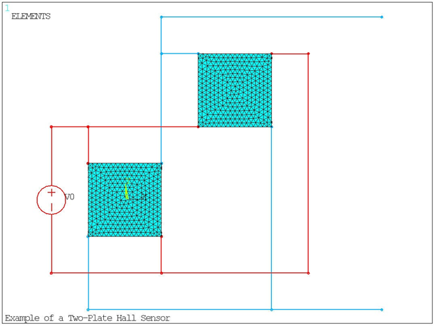
Electrical contacts are made on the plates by coupling the voltage of nodes (CP, VOLT) located within a small volume at each corner of the plates.
The plates are connected in parallel to a voltage source. The voltage load V0 = 3 V is applied by coupling the voltage (CP, VOLT) of the independent voltage source (CIRCU124 with KEYOPT (1) = 4) with the corresponding electrical contacts on the plates. A ground is created by setting the voltage of one electrical contact on each plate to zero (D,,VOLT).
The plates are connected to two terminals for measuring the output voltage. Corresponding electrical contacts on each plate are connected to the same terminal, as shown in Figure 6.10: Finite Element Model of the Two-Plate Hall Sensor. The connections for these terminals are created by coupling the voltage (CP,VOLT) of the appropriate electrical contacts on the plates.
Meshing facet elements (MESH200) are used to depict the presence of wires.
A series of static electromagnetic analyses is performed on the sensor to determine the Hall voltage. The first analysis is performed without any applied magnetic field to determine the offset voltage. The output voltage should be zero in the absence of a magnetic field. Due to non-uniform meshing, the current distribution is not symmetrical, resulting in a small potential difference (offset voltage) across the output pair of contacts. In a real application, the offset voltage can be caused by various factors, such as mechanical stresses, material inhomogeneities, or temperature variations.
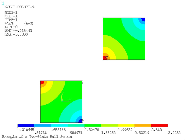
The initial electric potential distribution in the Hall plates is created by the applied voltage across the sensor, as shown in Figure 6.11: Electric Potential Distribution in the Plates.
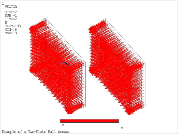
For the second static analysis, the output voltage is calculated when there is an applied magnetic field (0.8 T) perpendicular to the Hall plate, as shown in Figure 6.12: Vector Plot of Applied Magnetic Field on the Plates. The offset voltage is subtracted from this output voltage to determine the Hall voltage.
The magnetic field as measured by the sensor can be calculated by Eq. 9.14 in the reference:
Where:
I = the average current through the Hall plates. This value is retrieved using *GET.
c = the thickness of the plates.
VH = the Hall voltage from the sensor.
From the two-plate sensor measurement for Hall voltage, the applied magnetic field is calculated to be 0.788 T. The actual applied magnetic field is 0.8 T.
/title, Example of a Two Hall Plate Sensor
/NOPR

! *** Plate dimensions
a=3e-3			! Half plate length, m
b=3e-3			! Half plate height, m
c=0.4e-3			! Plate width, m

! *** Material properties for n-type InAs
Rh=-0.0001			! Hall coefficient, m^3/C
rho=1.6e-3			! Resistivity, Ohm*m
mu=1				! Relative magnetic permeability

! *** Load parameters
V=3				! Applied voltage, V
Bz=0.8			! Applied magnetic field, T

/PREP7
et,1,SOLID236,1		! Electromagnetic analysis, AZ+VOLT
mp,rh,1,Rh
mp,rsvx,1,rho
mp,murx,1,mu
block,-a,a,-b,b,0,c			! Hall plate 1
block,-a,-a+a/8,b,b-b/8,c/2,c	! Electrical contacts plate 1
block,-a,-a+a/8,-b,-b+b/8,c/2,c
block,a,a-a/8,b,b-b/8,c/2,c
block,a,a-a/8,-b,-b+b/8,c/2,c
block,2*a,4*a,2*b,4*b,0,c		! Hall plate 2
block,2*a,2*a+a/8,4*b,4*b-b/8,c/2,c	! Electrical contacts plate 2
block,2*a,2*a+a/8,2*b,2*b+b/8,c/2,c
block,4*a,4*a-a/8,2*b,2*b+b/8,c/2,c
block,4*a,4*a-a/8,4*b,4*b-b/8,c/2,c
esize,c
msha,1,3d				! Tetrahedral
vovlap,all
vmesh,all

! *** Voltage supply and wires
w1=node(-a,b,c)			! Nodes for wire modeling
w2=node(a,-b,c)
w3=node(a,b,c)
w4=node(-a,-b,c)
w5=node(2*a,2*b,c)
w6=node(4*a,4*b,c)
w7=node(4*a,2*b,c)
w8=node(2*a,4*b,c)

*get,n_max,node,,num,max	! Get max node number
n,n_max+1,-2*a,2*b,c		! Define nodes for voltage and wire elements
n,n_max+2,-2*a,,c
n,n_max+3,-2*a,-2*b,c
n,n_max+4,-a,2*b,c
n,n_max+5,a,-2*b,c
n,n_max+6,5*a,-2*b,c
n,n_max+7,5*a,4*b,c
n,n_max+8,a,4*b,c
n,n_max+9,-a,-3*b,c
n,n_max+10,4*a,-3*b,c
n,n_max+11,a,5*b,c
n,n_max+12,7*a,5*b,c
n,n_max+13,7*a,-3*b,c

et,2,CIRCU124,4			! Independent voltage source from CIRCU124
r,2,V
type,2
real,2
e,n_max+1,n_max+3,n_max+2
/icscale,,0.1

et,3,MESH200,0,0,0,0		! Wire from MESH200
type,3
e,n_max+1,n_max+4
e,n_max+4,w1
e,n_max+3,n_max+5
e,n_max+5,w2
e,n_max+5,n_max+6
e,n_max+6,n_max+7
e,n_max+7,w6
e,n_max+4,w5
e,w3,n_max+8
e,n_max+8,w8
e,w4,n_max+9
e,n_max+9,n_max+10
e,n_max+10,w7
e,n_max+8,n_max+11
e,n_max+11,n_max+12
e,n_max+10,n_max+13
/color,elem,12,3620,3628
/color,elem,5,3629,3636

! *** Boundary conditions and loads
vsel,s,volu,,11
vsel,a,volu,,16
nslv
nsel,a,node,,n_max+1
cp,1,volt,all			! Couple for voltage supply
vsel,s,volu,,14
vsel,a,volu,,18
nslv
nsel,a,node,,n_max+3
d,all,volt,0			! Ground
vsel,s,volu,,12
vsel,a,volu,,17
nslv
cp,2,volt,all			! Couple for output voltage
n1=ndnext(0)
vsel,s,volu,,13
vsel,a,volu,,15
nslv
cp,3,volt,all			! Couple for output voltage
n2=ndnext(0)
alls

dflx,all,,,0			! Set B-field in the +Z-direction to B=0 T
fini

/SOLU
outres,all,all
solve
Voff=volt(n2)-volt(n1)	! Offset voltage
esel,s,type,,1
nsle
dflx,all,,,Bz			! Create uniform B-field in the +Z-direction
alls
solve
fini

/POST1
vsel,s,volu,,11
nslv
fsum
*get,I_1,fsum,,ITEM,amps	! Current through plate 1
vsel,s,volu,,16
nslv
fsum
*get,I_2,fsum,,ITEM,amps	! Current through plate 2
alls
I_avg=(I_1+I_2)/2		! Average current through plates
/com
/com  -------------------- RESULTS --------------------
/com
/com  ***** Offset Voltage *****
/com
/com  Offset voltage:    %Voff% V
/com
/com
/com  ***** Total Output Voltage *****
/com
/com  Total output voltage (with magnetic field):    %volt(n2)-volt(n1)% V
/com
/com
/com  ***** Hall Voltage *****
/com
/com  Calculated Hall Voltage:     %volt(n2)-volt(n1)-Voff% V
/com
/com
/com  ***** Magnetic Field *****
/com
/com  Calculated Magnetic Field:     %((volt(n2)-volt(n1)-Voff)*c)/(Rh*I_avg)% T
/com  Applied Magnetic Field:        %Bz% T
/com
/com
fini
Another Ansys, Inc. publication, the Mechanical APDL Verification Manual, contains other examples of various types of analyses, including the following examples of 3D static edge-based magnetic analysis:


