VM214
VM214
Rotating Rod in a Uniform Magnetic Field
Test Case
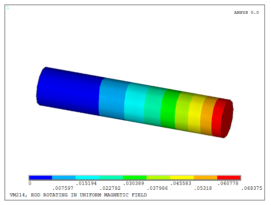
A conducting rod of length L (along the X-axis) and radius R is rotated about the Z-axis in a uniform magnetic field Bz with angular velocity Ωz. Determine the induced voltage difference V between the ends of the rod.

| Material Properties | Geometric Properties | Loading | ||||||
|---|---|---|---|---|---|---|---|---|
|
|
|
Analysis Assumptions and Modeling Notes
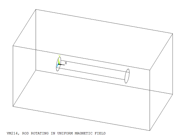
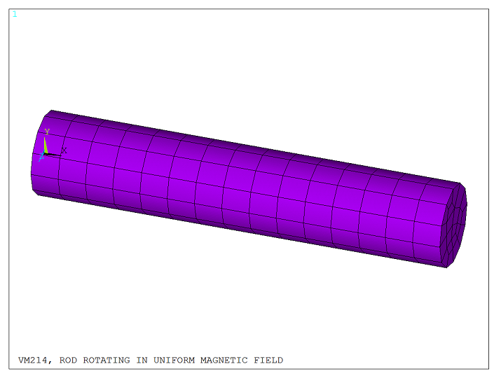
The model consists of a conducting rod surrounded by an open air box, as shown in Figure 341: Rotating Rod Surrounded by an Air Box. The rod is meshed with brick-shaped electromagnetic (KEYOPT(1) = 1) elements (SOLID236), and the surrounding air box with tetrahedron-shaped magnetic (KEYOPT(1) = 0) elements (SOLID236). Angular velocity Ωz is specified using the BF,,VELO load to take into account the velocity effects in the conducting rod. The uniform magnetic field Bz is defined using the DFLX command. One end of the rod is electrically ground (D,,VOLT,0).
A linear static electromagnetic analysis is performed to determine the voltage distribution in the rod. The calculated voltage at the free end of the rod agrees with the analytical solution for the induced EMF: