VM213
VM213
Differential Inductance of a Transformer
Test Case
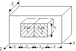
A transformer with a nonlinear iron core is wound with two separate
coils. Coil 1 is excited by a current of 0.2 A, while coil 2 is excited
by a current of 0.025 A. Calculate the differential self-inductance
of both coil 1 and 2, as well as the differential mutual inductance
between the two coils.
Analysis Assumptions and Modeling Notes
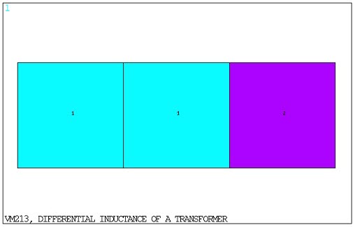
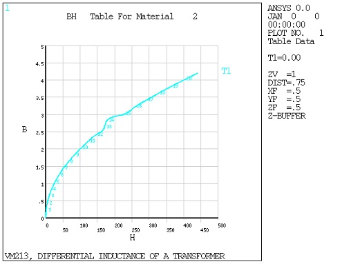
The half-symmetry model of the transformer consists of three
blocks, which represent coil 1, coil 2, and the nonlinear iron core.
The blocks are meshed using edge-based electromagnetic elements (SOLID236). A nonlinear magnetic static analysis is performed
first to determine the operating point (I1, I2). The nonlinear analysis
is followed by a linear perturbation magnetic static analysis with
three load steps (I1, I0), (I0,I2), and (I1, I2), to determine the
coil differential inductance with respect to an operating point (I1,I2).
The differential inductance matrix is derived from the incremental
energy of the system at these solution points. The incremental energy
is calculated using the IENE element record.