


VM241
VM241
Static Force Computation of a 3D Solenoid Actuator
Overview
| Reference: | N.Takahashi, T. Nakata, and H. Morishige, "Summary of Results for Problem 20 (3D Static Force Problem)", COMPEL, Vol.14 (1995), pp. 57-75. |
| Analysis Type(s): | Static (ANTYPE = 0) |
| Element Type(s): |
3D 20 node Electric Solid (SOLID231) 3D 10 node Tetrahedral Electric Solid (SOLID232) 3D 20 node Electromagnetic Solid (SOLID236) 3D 10 node Tetrahedral Electromagnetic Solid (SOLID237) Meshing Facet (MESH200) |
| Input Listing: |
VM241 requires a supplemental .cdb input file which is too long to include full input listings. This file must be downloaded and placed in your working directory for the test case to run properly. Additionally, the geometry and mesh should be regenerated. Download link: MAPDL Test Case Files for 2024 R2 vm241-1.cdb vm241-2.cdb |
Test Case
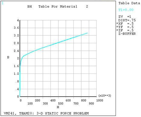
For the given solenoid actuator with an applied total coil current of 5000 A-turns, find the magnetic flux density (BZ) of the Pole, the magnetic flux density (BZ) of the Arm, and the Magnetic Force in the Z-direction. The center pole and yoke are made of steel characterized by the B-H curve shown in Figure 407: B-H Curve.
| Material Properties | Geometric Properties | Loading | |||||||||||
|---|---|---|---|---|---|---|---|---|---|---|---|---|---|
|
|
|
Analysis Assumptions and Modeling Notes
This analysis is based on the TEAM workshop problem 20. It utilizes the edge-flux element formulation with SOLID236 and tetrahedral SOLID237 elements. To simplify meshing, the SMRTSIZE option was used to automatically determine line divisions and spacing ratios while taking into account the line proximity effects. Mesh density can be adjusted using the SMT parameter, for this case, a SMT level of 10 was applied.
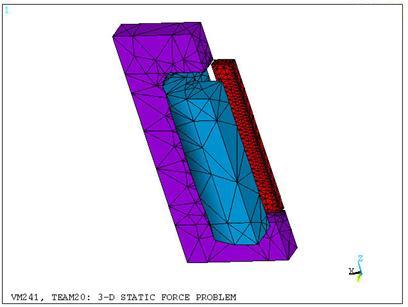
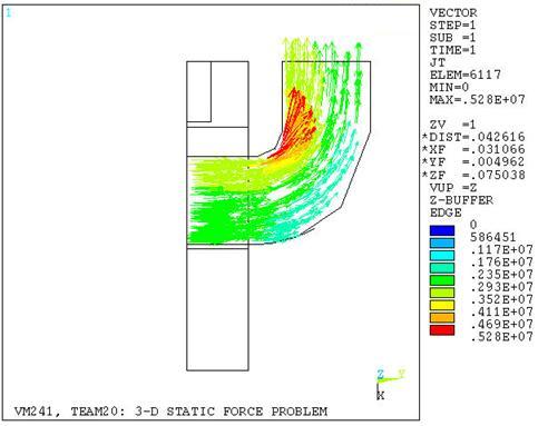
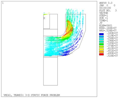
The static analysis is performed using a quarter symmetry model (Figure 408: Finite Element Model with SOLID232 and SOLID237 Elements). The current source density in the coil (Figure 409: Current Density in the Coil with SOLID232 and SOLID237 Elements) was modeled using the electric tetrahedral SOLID231 and SOLID232 and elements and transferred to the magnetic element SOLID236 and SOLID237 respectively via LDREAD.
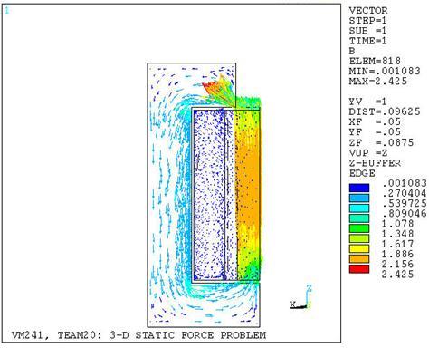
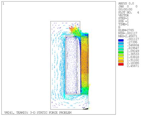
The calculated magnetic field B in the armature is shown in Figure 410: Magnetic Field Flux Density with SOLID232 and SOLID237 Elements. To calculate the total magnetic force acting on the pole, all the nodes and elements of component ARM were selected for FMAG force summation. Note that for more accurate results, the option to output magnetic element forces FMAG at the corner nodes (KEYOPT (7) =1 with SOLID236 and SOLID237) was used.
Results Comparison
| SOLID236 | |||
|---|---|---|---|
| Total Current = 5000 A-turns | Target | Mechanical APDL | Ratio |
| Magnetic Force (N) | 80.100 | 79.495 | 0.992 |
| Pole Flux Density (BZ, Tesla) | 0.460 | 0.451 | 0.981 |
| Arm Flux Density (BZ, Tesla) | 2.050 | 2.029 | 0.990 |
| SOLID237 | |||
|---|---|---|---|
| Total Current = 5000 A-turns | Target | Mechanical APDL | Ratio |
| Magnetic Force (N) | 80.100 | 79.495 | 0.992 |
| Pole Flux Density (BZ, Tesla) | 0.460 | 0.451 | 0.981 |
| Arm Flux Density (BZ, Tesla) | 2.050 | 2.029 | 0.990 |