The following examples are available:
The following example is a 2D static magnetic analysis of a solenoid actuator.
The example analysis, based on a solenoid actuator, analyzes the actuator as a 2D axisymmetric model. The example calculates the force on the armature (the moving component of the actuator) and the inductance of the coil. Figure 2.7: Diagram of a Solenoid Actuator below shows you the solenoid actuator:
The analysis uses the parameters listed below to model the actuator geometry:
| Parameter | Description |
|---|---|
| Number of turns in the coil; used in postprocessing | |
| I=1.0 | Current per turn |
| ta=.75 | Thickness of inner leg of magnetic circuit |
| tb=.75 | Thickness of lower leg of magnetic circuit |
| tc=.50 | Thickness of outer leg of magnetic circuit |
| td=.75 | Armature thickness |
| wc=1 | Width of coil |
| hc=2 | Height of coil |
| gap=.25 | Gap |
| space=.25 | Space around coil |
| ws=wc+2*space | |
| hs=hc+.75 | |
| w=ta+ws+tc | Total width of model |
| hb=tb+hs | |
| h=hb+gap+td | Total height of model |
| acoil=wc*hc | Coil area |
| jdens=n*i/acoil | Current density of coil |
The magnetic flux that the coil current produces is assumed to be small enough that no saturation of the iron occurs. This allows a single iteration linear analysis. To simplify the example model, the flux leakage out of the iron at the perimeter of the model is assumed to be minimal. Under normal conditions, the model would include air surrounding the iron to model the effects of flux leakage.
Because no leakage is assumed at the perimeter of the model, the flux flows parallel to the surface. You enforce this by placing a "flux parallel" condition around the model.
For a static (DC) current, you may enter the current in the form of current density over the area of the coil. The APDL is used to compute the current density from the number of turns, the current per turn, and the coil area. The armature is flagged for a force calculation.
In postprocessing, the forces are summarized for the armature, using both a Maxwell stress tensor and a virtual work calculation. Flux density also is displayed. The final postprocessing operation computes the terminal parameters including coil inductance.
Note: The example analysis is only one of many possible 2D static magnetic analyses. Not all such analyses follow exactly the same steps or perform those steps in the same sequence. The properties of the material or materials being analyzed and the conditions surrounding those materials determine which steps a specific analysis needs to include.
For a detailed step-by-step procedure for the magnetic analysis of a solenoid actuator, see the Electromagnetics Tutorial on the Ansys customer site.
You can perform the example static analysis of a solenoid actuator using the commands shown below rather than via the GUI method. All text prefaced by an exclamation point (!) is a comment.
/PREP7
/TITLE, 2D Solenoid Actuator Static Analysis


ET,1,PLANE233               ! Define PLANE233 as element type
KEYOPT,1,3,1                ! Use axisymmetric analysis option
KEYOPT,1,7,1                ! Condense forces at the corner nodes
MP,MURX,1,1                 ! Define material properties (permeability)
MP,MURX,2,1000              ! Permeability of backiron
MP,MURX,3,1                 ! Permeability of coil
MP,MURX,4,2000              ! Permeability of armature


/com,                       ! Set parameter values for analysis
n=650                       ! Number of coil turns
i=1.0                       ! Current per turn
ta=.75                      ! Model dimensions (centimeters)
tb=.75
tc=.50
td=.75
wc=1
hc=2
gap=.25
space=.25
ws=wc+2*space
hs=hc+.75
w=ta+ws+tc
hb=tb+hs
h=hb+gap+td
acoil=wc*hc                 ! Cross-section area of coil (cm**2)
jdens=n*i/acoil             ! Current density (A/cm**2)

/PNUM,AREA,1
RECTNG,0,w,0,tb             ! Create rectangular areas
RECTNG,0,w,tb,hb
RECTNG,ta,ta+ws,0,h
RECTNG,ta+space,ta+space+wc,tb+space,tb+space+hc
AOVLAP,ALL
RECTNG,0,w,0,hb+gap
RECTNG,0,w,0,h
AOVLAP,ALL
NUMCMP,AREA                 ! Compress out unused area numbers
APLOT

ASEL,S,AREA,,2              ! Assign attributes to coil
AATT,3,1,1,0
ASEL,S,AREA,,1              ! Assign attributes to armature
ASEL,A,AREA,,12,13
AATT,4,1,1
ASEL,S,AREA,,3,5            ! Assign attributes to backiron
ASEL,A,AREA,,7,8
AATT,2,1,1,0
/PNUM,MAT,1                 ! Turn material numbers on
ALLSEL,ALL
APLOT                       ! Plot areas

SMRTSIZE,4                  ! Set smart size meshing level 4 (fine)
AMESH,ALL                   ! Mesh all areas
ESEL,S,MAT,,4               ! Select armature elements
CM,ARM,ELEM                 ! Define armature as a component
ALLSEL,ALL
ARSCAL,ALL,,,.01,.01,1,,,1  ! Scale model to MKS (meters)
FINISH

/SOLU
ESEL,S,MAT,,3               ! Select coil elements
BFE,ALL,JS,1,,,jdens/.01**2 ! Apply current density (A/m**2)
ESEL,ALL
NSEL,EXT                    ! Select exterior nodes
D,ALL,AZ,0                  ! Set potentials to zero (flux-parallel)
ALLSEL,ALL
SOLVE
FINISH

/POST1
PLF2D                       ! Plot flux lines in the model

CMSEL,S,'ARM'
NSLE                        ! Select nodes attached to the armature
ESLN                        ! Select elements attached to the selected nodes
EMFT                        ! Summarize magnetic forces
ALLSEL,ALL
PLVECT,B,,,,VECT,ELEM,ON    ! Plot flux density as vectors
/GRAPHICS,POWER             ! Turn PowerGraphics on
AVRES,2                     ! Don't average results across materials
PLNSOL,B,SUM                ! Plot flux density magnitude
FINISH
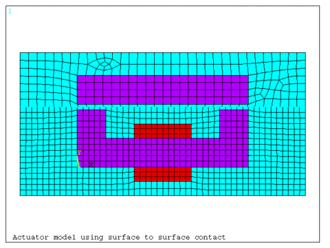
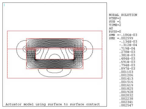
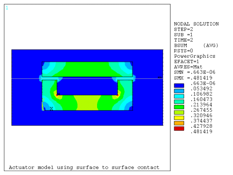
This example presents a 2D model of a coil actuator that demonstrates the use of surface-to-surface contact. Contact is typically used when multiple runs are required with re-positioning of a pole piece in a static or transient analysis, or for convenience in meshing regions with non-connecting meshes.
The contact region is located at the mid-span of the air gap. Two independent meshes are created; one for the lower portion of the model consisting of the back iron, coil, and lower air, and the upper portion consisting of the pole and the upper air. Target elements (TARGE169) are created using the ESURF command on the upper air elements at the air gap (coarser mesh). Contact elements (CONTA172) are created using the ESURF command on the lower air elements at the air gap (finer mesh). The MPC option is selected using bonded contact.
/prep7
/title, Actuator model using surface to surface contact

et,1,233                    ! plane233
et,2,169                    ! Target
et,3,172,7,2,,2             ! Contact, MPC option
keyopt,3,12,5               ! Bonded contact

mp,murx,1,1

tb,bh,2,,40                 ! BH curve
tbpt,,355,.7
,,405,.8
,,470,.9
,,555,1.
,,673,1.1
,,836,1.2
,,1065,1.3
,,1220,1.35
,,1420,1.4
,,1720,1.45
,,2130,1.5
,,2670,1.55
,,3480,1.6
,,4500,1.65
,,5950,1.70
,,7650,1.75
,,10100,1.8
,,13000,1.85
,,15900,1.9
,,21100,1.95
,,26300,2.
,,32900,2.05
,,42700,2.1
,,61700,2.15
,,84300,2.2
,,110000,2.25
,,135000,2.3
,,200000,2.41
,,400000,2.69
,,800000,3.22

mp,murx,3,1                 ! coil

! create backiron
rectng,0,.06,0,.01
rectng,0,.01,.01,.02
rectng,.05,.06,.01,.02


! create coil
rectng,.02,.04,-.005,0
rectng,.02,.04,.01,.015
aglue,all

! create lower air domain
rectng,-.02,.08,-.01,.021
aovlap,all
numcmp,area
cm,lower,area

! create pole
rectng,0,.06,.022,.032

! create upper air
rectng,-.02,.08,.021,.04
aovlap,7,8
asel,s,area,,7,9
cm,upper,area

asel,s,area,,4,6
aatt,2,1,1                  ! backiron
asel,s,area,,7
aatt,2,1,1                  ! pole
asel,s,area,,2,3
aatt,3,1,1                  ! coil


cmsel,s,lower
esize,.002
amesh,all
cmsel,s,upper
esize,.003
amesh,all

esla,s
nsle,s
nsel,r,loc,y,.021
real,2                      ! target element needs a real constant ID
type,2
esurf                       ! mesh target elements

cmsel,s,lower
esla,s
nsle,s
nsel,r,loc,y,.021
type,3
esurf                       ! mesh contact elements
allsel,all

nsel,s,loc,x,-.02
nsel,a,loc,x,.08
nsel,a,loc,y,-.01
nsel,a,loc,y,.04
d,all,az,0                  ! flux parallel

asel,s,area,,3
esla,s
bfe,all,js,,,,5e6           ! coil current density
asel,s,area,,2
esla,s
bfe,all,js,,,,-5e6
allsel,all
finish

/solu
solve
finish

/post1
plf2d
plnsol,b,sum
fini
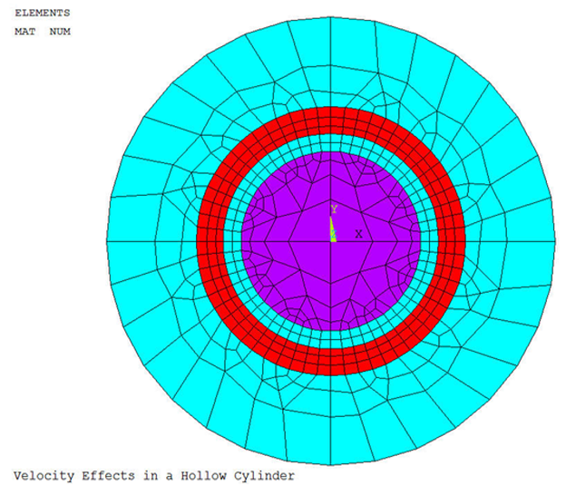
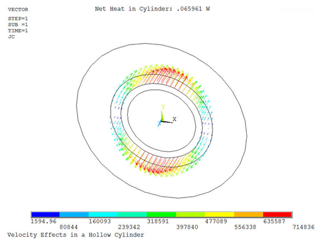
This example demonstrates the use of the velocity effects in a 2D model of a hollow conductive cylinder rotating around a stationary permanent magnet.
A long conductive hollow cylinder rotates about its axis. A stationary solid cylindrical permanent magnet resides with the hollow rotating one. The two bodies are concentric, and the permanent magnet is poled in a direction normal to its axis. The ends of the rotating hollow cylinder are electrically insulated, so the net current flowing in the axial direction is zero (open terminal conductor).
The objective is to determine the Joule heat per unit length in the rotating conductive cylinder and display the eddy currents induced in it by the velocity effects. The evaluation is made half-way along the length of the rotating cylinder, well away from insulated ends where the induced current will reverse direction and have significant non-axial components.
/title, Velocity Effects in a Hollow Cylinder
/nopr
/pnu,mat,1
/num,1

C*********************************************************
C*** PARAMETERS
C*********************************************************
pi=acos(-1)

r_PM=0.010
r1_cyl=0.012
r2_cyl=0.015
r_dmn=0.025

l=0.050

Hc_PM=1e6
mur_PM=1.04

rsv_cyl=3e-8
mur_cyl=1

omga=50	        ! ANGULAR VELOCITY, RPM


C*********************************************************
C*** GEOMETRY
C*********************************************************
/prep7

asel,none
pcir,r_PM,,0,90
aatt,2,2,2

asel,none
pcirc,r1_cyl,r2_cyl,0,90
aatt,3,3,3

alls
cm,keep_a,area

asel,none
pcirc,r_dmn,,0,90
cm,scrap_a,area

alls
asba,scrap_a,keep_a,,dele,keep
cmse,u,keep_a
aatt,1,1,1

alls
aplo


C*********************************************************
C*** ATTRIBUTES, MESH
C*********************************************************
et,1,233
mp,murx,1,1

et,2,233
mp,murx,2,mur_PM
mp,mgyy,2,Hc_PM

et,3,233,1		! CYLINDER
mp,murx,3,mur_cyl
mp,rsvx,3,rsv_cyl

alls
ames,all

csys,1
agen,4,all,,,0,90,0
numm,node,1e-8,1e-8
numm,kp,1e-8,1e-8


C*********************************************************
C*** BCs
C*********************************************************
alls
nsel,s,ext
d,all,az

esel,s,mat,,3
nsle
cp,1,volt,all
alls

C*********************************************************
C*** LOAD
C*********************************************************
bf,all,velo,,,,,,omga*(2*pi)/60   ! Angular velocity, rad/sec

C*********************************************************
C*** SOLVE
C*********************************************************
/solu
solve
fini

C*********************************************************
C*** RESULTS
C*********************************************************
/post1
set

etab,,jhea
etab,,volu
smul,ht,jhea,volu
ssum

*get,ht_total,ssum,,item,ht
ht_total=ht_total*l

/ann,dele
/tla,-0.25,0.90, Net Heat in Cylinder: %ht_total% W

/vie,1,1,2,3
plve,jc,,,,vect,,on

/com,
/com,  Net Heat in Cylinder: %ht_total% W
/com,
fini
Another Ansys, Inc., publication, the Mechanical APDL Verification Manual, contains several additional examples of 2D static magnetic analyses:


