VM165
VM165
Current-Carrying Ferromagnetic Conductor
Overview
Test Case
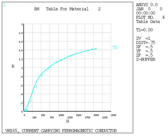
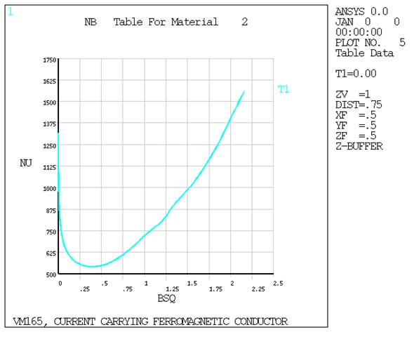
A long cylindrical shell of cast steel carries a constant current I uniformly distributed within the conductor cross-section. Determine the tangential magnetic flux density Bθ at several locations within the conductor.

| Material Properties | Geometric Properties | Loading | |||||
|---|---|---|---|---|---|---|---|
|
|
|
Analysis Assumptions and Modeling Notes
The conductor is assumed to be infinitely long, thus end effects can be ignored allowing for a two-dimensional planar analysis. Since the field is symmetric around the circumference, only a single, one-element width slice is chosen for modeling. The circumferential width of the slice is chosen as 5° to produce reasonable element aspect ratios. The external air is modeled to a radius of 0.75 inches. Infinite solid elements are used from there to a radius of 1.5 inches to model the far-field decay.
The MKS system of units is used for the analysis. The conversion
factor, 0.0254, used in the KPSCALE command, converts the geometry input units
from inches to meters. The current density is calculated as  = 2.28019 x 10⁻⁴ A/in2 =
438559 A/m2.
= 2.28019 x 10⁻⁴ A/in2 =
438559 A/m2.