VM270
VM270
Forces in Permanent Magnets
Overview
Test Case
Axial force is calculated between the coaxial magnet and coil shown in Figure 469: Coil and Magnet Configuration. The magnet is made up of Samarium-Cobalt and the coil is wound on a nonmagnetic form (brass). The magnitude of the DC-current energizing the coil is 50mA. The forces are computed at an axial distance of 0.234mm between the magnet and coil.

| Material Properties | Geometric Properties | Loading |
Air: Magnetic relative permeability (MURX) = 1 Copper: Magnetic relative permeability (MURX) = 1 Magnet (Samarium-Cobalt): Remanence (BR) = 1.02T Magnetic relative permeability (MURX) = 1.126894 Magnetic coercive force (HC) = 720000A/m Magnetic relative permeability (MURX) = BR/(HC*MUZRO) = 1.126894 where MUZRO = 4πe-7H/m Infinite elements (air): Magnetic relative permeability (MURX) = 1 | Spool inner diameter (D1) = 3.048mm Spool outer diameter (D2) = 3.9624mm Inner length (L1) = 1.524mm Spool thickness (t) = 0.127mm Axial displacement (δ) = 0.234mm Diameter of magnet (D3) = 2.9972mm Length of magnet (L3) = 1.6mm | Coil: Total current (I) = 50mA Resistance (R) = 57Ohm Number of turns (N) = 280 Current density (JS) = N*I/(D2/2-D1/2)/L1A/m2 |
Analysis Assumptions and Modeling Notes
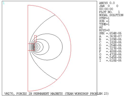
Two axisymmetric magnetostatic analyses are performed to determine the axial force (Fy) acting on the magnet and the coil respectively. The magnet, the coil, and the surrounding air are modeled with 2D PLANE233 elements. Open magnetic boundaries (see Figure 470: Flux Lines) are modeled with 2D INFIN110 quadratic elements. The coil is loaded with constant current density JS (BFE,,JS) derived from the total current I = 50 mA and the coil parameters.
The first analysis calculates the total axial force acting on the magnet as a sum of Maxwell forces in the magnet and in the surrounding air. To obtain a more accurate total force, the option to condense magnetic forces at the element corner nodes (KEYOPT(7) = 1) is activated on the PLANE233 element type. Element forces are summed up using the EMFT command. Note that when Maxwell forces are summed up, all the nodes in the region of interest and all the elements attached to these nodes should be selected.
The second analysis determines the axial force acting on the coil using the Lorentz force element option (KEYOPT(8) = 1). This option is applicable to conducting solids only and can be used as an alternative to the Maxwell force option. When summing up Lorentz forces using EMFT, only the nodes in the conducting region need to be selected.