VM172
VM172
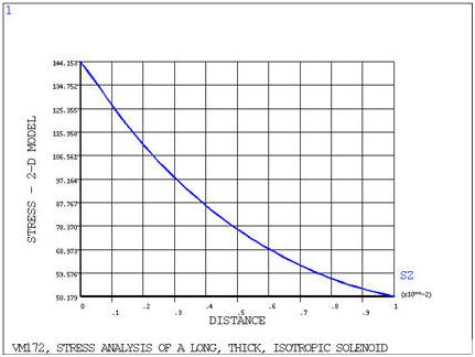
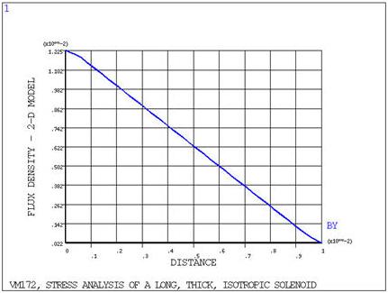
Stress Analysis of a Long, Thick, Isotropic Solenoid
Test Case
A long, thick solenoid carries a uniform current density distribution, J. Assuming that the turns of the solenoid can be modeled as a homogeneous isotropic material with modulus of elasticity E, and Poisson's ratio ν, determine the axial magnetic flux density distribution Bθ and the circumferential stress σo distribution in the solenoid.

| Material Properties | Geometric Properties | Loading | ||||||||
|---|---|---|---|---|---|---|---|---|---|---|
|
|
|
Analysis Assumptions and Modeling Notes
The problem is solved first using PLANE13 elements. The length of the
solenoid is assumed infinite (L =  ), so only a section of the axisymmetric solenoid (t = .002 m, arbitrary) is
required for modeling. It is assumed that the magnetic field external to the solenoid is zero, so
the nodes at x = b are coupled (AZ = constant) such that the proper flux-parallel boundary
condition is imposed. The flux-parallel condition at x = 0 is imposed by setting A = 0.
Flux-normal boundary conditions are imposed naturally (no Ansys input necessary) at y = 0
and y = t.
), so only a section of the axisymmetric solenoid (t = .002 m, arbitrary) is
required for modeling. It is assumed that the magnetic field external to the solenoid is zero, so
the nodes at x = b are coupled (AZ = constant) such that the proper flux-parallel boundary
condition is imposed. The flux-parallel condition at x = 0 is imposed by setting A = 0.
Flux-normal boundary conditions are imposed naturally (no Ansys input necessary) at y = 0
and y = t.
Symmetric structural boundary conditions are applied to the solenoid elements at y = 0. The nodes at y = t on the solenoid are coupled in UY to ensure symmetry. The air is modeled with 5 elements in the radial direction while the solenoid is discretized with 20 elements in the radial direction to accurately model the stress distribution.