


PLANE293
2D 8-Node Thermal Solid
PLANE293 Element Description
PLANE293 is a higher order version of the 2D, 4-node thermal element (PLANE292). The element has one degree of freedom, temperature, at each node. The 8-node elements have compatible temperature shapes and are well suited to model curved boundaries.
The 8-node thermal element is applicable to a 2D, steady-state or transient thermal analysis. See PLANE293 - 2D 8-Node Thermal Solid in the Theory Reference for more details about this element. If the model containing this element is also to be analyzed structurally, the element should be replaced by an equivalent structural element (such as PLANE183).
PLANE293 Input Data
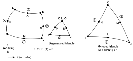
The geometry, node locations, and the coordinate system for this element are shown in Figure 293.1: PLANE293 Geometry. The element is defined by eight nodes and orthotropic material properties. A triangular-shaped element may be formed by defining the same node number for nodes K, L and O. It is also possible to define a 6-noded triangle via KEYOPT(1) = 1.
Orthotropic material directions correspond to the element coordinate directions. The element coordinate system orientation is as described in Coordinate Systems. Specific heat and density are ignored for steady-state solutions. Properties not input default as described in the Material Reference.
Element loads are described in Element Loading. Convection or heat flux (but not both) and radiation may be input as surface loads at the element faces as shown by the circled numbers on Figure 293.1: PLANE293 Geometry. Heat generation rates may be input as element body loads at the nodes. If the node I heat generation rate HG(I) is input, and all others are unspecified, they default to HG(I). If all corner node heat generation rates are specified, each midside node heat generation rate defaults to the average heat generation rate of its adjacent corner nodes.
This element can also have a Z-depth specified by KEYOPT(3) and real constant THK. Be careful when using this option with other physics, especially radiation. Radiation view factors will be based on a unit Z-depth (only).
A summary of the element input is given in "PLANE293 Input Summary". A general description of element input is given in Element Input.
PLANE293 Input Summary
- Nodes
I, J, K, L, M, N, O, P
- Degrees of Freedom
TEMP
- Real Constants
THK = Thickness (used only if KEYOPT(3) = 3)
- Material Properties
TB command: See Element Support for Material Models for this element. MP command: KXX, KYY, DENS, C, ENTH - Surface Loads
- Convection or Heat Flux (but not both) and Radiation (using Lab = RDSF) --
face 1 (J-I), face 2 (K-J), face 3 (L-K), face 4 (I-L) when KEYOPT(1) = 0 (8-noded quadrilateral and triangle)
face 1 (J-I), face 2 (K-J), face 3 (I-K) when KEYOPT(1) = 1 (6-noded triangle)
- Body Loads
- Heat Generations --
HG(I), HG(J), HG(K), HG(L), HG(M), HG(N), HG(O), HG(P) when KEYOPT(1) = 0 (8-noded quadrilateral and triangle)
HG(I), HG(J), HG(K), HG(L), HG(M), HG(N) when KEYOPT(1) = 1 (6-noded triangle)
- Special Features
- KEYOPT(1)
- 0 --
8-noded quadrilateral and triangle
- 1 --
6-noded triangle
- KEYOPT(3)
Element behavior:
- 0 --
Plane
- 1 --
Axisymmetric
- 3 --
Plane with Z-depth, specified via real constant THK.
- KEYOPT(11)
Film coefficient matrix:
- 0 --
Program determines whether to use a diagonal or consistent film coefficient matrix.
- 1 --
Use a diagonal film coefficient matrix (default).
- 2 --
Use a consistent film coefficient matrix.
- KEYOPT(15)
Specific heat matrix:
- 0 --
Program determines whether to use a diagonal or consistent specific heat matrix.
- 1 --
Use a diagonal specific heat matrix.
- 2 --
Use a consistent specific heat matrix (default).
- KEYOPT(16)
Evaluation of material properties:
- 0 --
Evaluate material properties at centroid (default).
- 1 --
Evaluate material properties at each integration point.
Note: If THOPT,QUASI has been issued, KEYOPT(16) is ignored and material properties are evaluated at the centroid.
PLANE293 Output Data
The solution output associated with the element is in two forms:
Nodal temperatures included in the overall nodal solution
Additional element output as shown in Table 293.1: PLANE293 Element Output Definitions
The element output directions are parallel to the element coordinate system. For an axisymmetric analysis the face area and the heat flow rate are on a full 360° basis. Convection heat flux is positive out of the element; applied heat flux is positive into the element. A general description of solution output is given in Solution Output. See the Basic Analysis Guide for ways to view results.
The Element Output Definitions table uses the following notation:
A colon (:) in the Name column indicates that the item can be accessed by the Component Name method (ETABLE, ESOL). The O column indicates the availability of the items in the file jobname.out. The R column indicates the availability of the items in the results file.
In either the O or R columns, “Y” indicates that the item is always available, a letter or number refers to a table footnote that describes when the item is conditionally available, and “-” indicates that the item is not available.
Table 293.1: PLANE293 Element Output Definitions
| Name | Definition | O | R |
|---|---|---|---|
| EL | Element Number | Y | Y |
| NODES | Nodes - I, J, K, L, M, N, O, P or I, J, K, L, M, N | Y | Y |
| MAT | Material number | Y | Y |
| VOLU: | Volume | Y | Y |
| XC, YC | Location where results are reported | Y | 2 |
| HGEN | Heat generations HG(I), HG(J), HG(K), HG(L), HG(M), HG(N), HG(O), HG(P) or HG(I), HG(J), HG(K), HG(L), HG(M), HG(N) | Y | - |
| TG:X, Y, SUM | Thermal gradient components and vector sum at centroid | Y | Y |
| TF:X, Y, SUM | Thermal flux (heat flow rate/cross-sectional area) components and vector sum at centroid | Y | Y |
| FACE | Face label | 1 | - |
| NODES | Face nodes | 1 | - |
| AREA | Face area | 1 | 1 |
| HFILM | Film coefficient | 1 | - |
| TAVG | Average face temperature | 1 | 1 |
| TBULK | Fluid bulk temperature | 1 | - |
| HEAT RATE | Heat flow rate across face by convection | 1 | 1 |
| HEAT RATE/AREA | Heat flow rate per unit area across face by convection | 1 | - |
| HFAVG | Average film coefficient of the face | - | 1 |
| TBAVG | Average face bulk temperature | - | 1 |
| HFLXAVG | Heat flow rate per unit area across face caused by input heat flux | - | 1 |
| HFLUX | Heat flux at each node of face | 1 | - |
Available only at centroid as a *GET item.
Table 293.2: PLANE293 Item and Component Labels (KEYOPT(1) = 0) and Table 293.3: PLANE293 Item and Component Labels (KEYOPT(1) = 1) list output available through the ETABLE command using the Sequence Number method. See The General Postprocessor (POST1) in the Basic Analysis Guide and The Item and Sequence Number Table of this reference for more information. The following notation is used in the tables below:
- Name
output quantity as defined in the Table 293.1: PLANE293 Element Output Definitions
- Item
predetermined Item label for ETABLE command
- FCn
sequence number for solution items for element Face n
PLANE293 Assumptions and Restrictions
The area of the element must be positive.
The 2D element must lie in an X-Y plane as shown in Figure 293.1: PLANE293 Geometry and the Y-axis must be the axis of symmetry for axisymmetric analyses.
An axisymmetric structure should be modeled in the +X quadrants.
A face with a removed midside node implies that the temperature varies linearly, rather than parabolically, along that face. See Quadratic Elements (Midside Nodes) in the Modeling and Meshing Guide for more information about the use of midside nodes.
If the thermal element is to be replaced by a PLANE183 structural element with surface stresses requested, the thermal element may be oriented such that face IJ and/or face KL is a free surface. A free surface of the element (that is, not adjacent to another element and not subjected to a boundary constraint) is assumed to be adiabatic.
Thermal transients having a fine integration time step and a severe thermal gradient at the surface will require a fine mesh at the surface.
Plotting temperature in /POST1 is based on corner nodes only. To include midside nodes in the plot, issue /EFACET,2 before PLNSOL,TEMP.
If enthalpy is defined, density and specific heat will be ignored.