


| Matrix or Vector | Element configuration | Shape Functions | Integration Points |
|---|---|---|---|
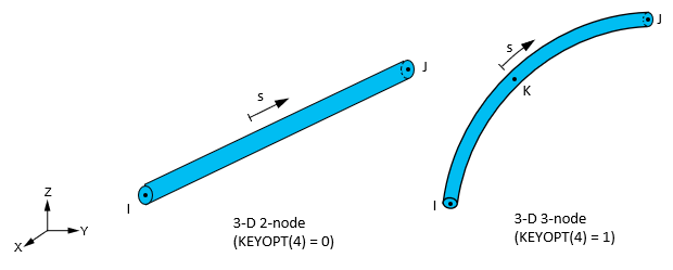
| Conductivity and Specific Heat Matrices; and Heat Generation Load Vector | 2-node (KEYOPT(4) = 0) | Equation 11–13 | None |
| 3-node (KEYOPT(4) = 1) | Equation 11–25 | 3 |
Heat Flow describes the derivation of thermal element matrices and load vectors as well as heat flux evaluations.
The conductivity matrix is:
 | (13–27) |
where:
| A = area (input as AREA on R command) |
 = conductivity along longitudinal s direction (input as KXX on
MP command) = conductivity along longitudinal s direction (input as KXX on
MP command) |
| L = distance between nodes |
The specific heat matrix is:
 | (13–28) |
where:
This specific heat matrix is a diagonal matrix with each diagonal being the sum of the corresponding row of a consistent specific heat matrix. The heat generation load vector is:
 | (13–29) |
where:

|
A closed-form representation of the matrices and load vector is not available since integration rules are used to evaluate them.
For the 3-node element, the specific heat matrix is a full matrix (not a diagonal matrix).

