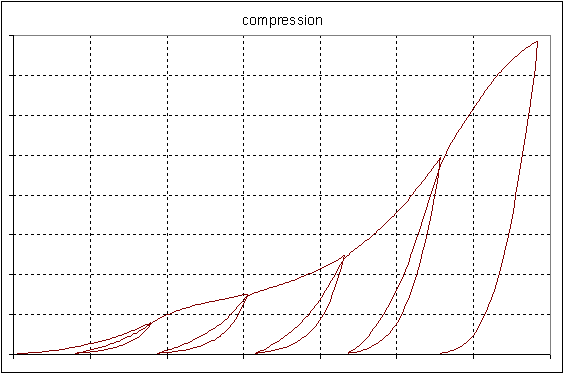
Gasket joints are essential components in most of structural assemblies. Gaskets as sealing components between structural components are usually very thin and made of many materials, such as steel, rubber and composites. From a mechanics point of view, gaskets act to transfer the force between mating components. The gasket material is usually under compression. The material under compression exhibits high nonlinearity. The gasket material also shows quite complicated unloading behavior. The primary deformation of a gasket is usually confined to 1 direction, that is through-thickness. The stiffness contribution from membrane (in-plane) and transverse shear are much smaller, and are neglected.
The table option GASKET allows gasket joints to be simulated with the interface elements, in which the through-thickness deformation is decoupled from the in-plane deformation, see INTER192 - 2D 4-Node Gasket, INTER193 - 2D 6-Node Gasket, INTER194 - 3D 16-Node Gasket, and INTER195 - 3D 8-Node Gasket for detailed description of interface elements. The user can directly input the experimentally measured complex pressure-closure curve (compression curve) and several unloading pressure-closure curves for characterizing the through thickness deformation of gasket material.
Figure 4.22: Pressure vs. Deflection Behavior of a Gasket Material shows the experimental pressure vs. closure (relative displacement of top and bottom gasket surfaces) data for a graphite composite gasket material. The sample was unloaded and reloaded 5 times along the loading path and then unloaded at the end of the test to determine the unloading stiffness of the material.
The gasket pressure and deformation are based on the local element coordinate systems. The gasket pressure is actually the stress normal to the gasket element midsurface in the gasket layer. Gasket deformation is characterized by the closure of top and bottom surfaces of gasket elements, and is defined as:
(4–126) |
Where, uTOP and uBOTTOM are the displacement of top and bottom surfaces of interface elements in the local element coordinate system based on the mid-plane of element.
The input of material data of a gasket material is specified by the command (TB,GASKET). The input of material data considers of 2 main parts: general parameters and pressure closure behaviors. The general parameters defines initial gasket gap, the stable stiffness for numerical stabilization, and the stress cap for gasket in tension. The pressure closure behavior includes gasket compression (loading) and tension data (unloading).
The GASKET option has followings sub-options:
| Sub-option | Description |
|---|---|
| PARA | Define gasket material general parameters |
| COMP | Define gasket compression data |
| LUNL | Define gasket linear unloading data |
| NUNL | Define gasket nonlinear unloading data |
A gasket material can have several options at the same time. When no unloading curves are defined, the material behavior follows the compression curve while it is unloaded.
The thermal deformation is taken into account by using an additive decomposition in the total deformation, d, as:
(4–127) |
where:
| d = relative total deformation between top and bottom surfaces of the interface element |
| di = relative deformation between top and bottom surfaces causing by the applying stress, this can be also defined as mechanical deformation |
| dth = relative thermal deformation between top and bottom surfaces due to free thermal expansion |
| do = initial gap of the element and is defined by sub-option PARA |
The thermal deformation causing by free thermal expansion is defined as:
(4–128) |
where:
| α = coefficient of thermal expansion (input as ALPX on MP command) |
| ΔT = temperature change in the current load step |
| h = thickness of layer at the integration point where thermal deformation is of interest |


