


FLUID218
3D Hydrodynamic Bearing Element
FLUID218 Element Description
FLUID218 is a 3D element for modeling viscous fluid flow located between a cylindrical rotating part (the shaft or bearing journal) and a larger cylindrical stationary part (the bearing sleeve). It can be used to determine the pressure distribution in a cylindrical journal hydrodynamic bearing or squeeze film damper, or to perform a transient simulation of a rotor-bearing model.
The element behavior is based on the Reynolds equation. The following assumptions apply:
The flow is laminar and continuous.
The fluid-inertia effects are negligible.
The thickness of the fluid is very small compared to other dimensions of the fluid domain.
No slipping exists between the fluid film and the walls.
The fluid is typically incompressible, but density variation with respect to pressure, temperature, or location can be included. Also, the fluid is generally Newtonian, but viscosity variation with respect to pressure, temperature, or location can be included.
As a fluid-only element (PRES degree of freedom), FLUID218 can be used in a static analysis only. Pressure distribution is calculated based on the equilibrium position of the shaft center given by the real constants (displacements and velocities). If the viscosity or density is variable with the pressure, the analysis is nonlinear and the full Newton-Raphson solution method (NROPT,FULL) is necessary.
As a coupled-field element (PRES and U degrees of freedom), FLUID218 can be used in a nonlinear large-deflection (NLGEOM,ON) transient analysis only. Pressure distribution is calculated based on the instantaneous position of the shaft. Pressure forces are applied to the underlying structural part.
For more information, see FLUID218 - 3D Hydrodynamic Bearing Element in the Theory Reference.
FLUID218 Input Data
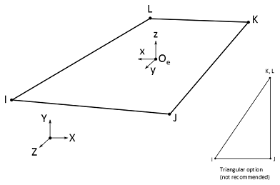
The geometry, node locations, and the coordinate system for this fluid element are shown in Figure 218.1: FLUID218 Geometry. The element is defined by four corner nodes. As the length of the bearing is along the global Z-axis, the element should be oriented such that the element normal (z-axis) is parallel to the global XY plane and its direction is outward of the shaft. The global Z-axis is referred to as the axial direction of the bearing and is coincident with the element y-axis. The element x-axis is the direction tangential to the bearing. It is in the element plane.
The element represents the whole fluid film so the mesh must consist of only one element across the film fluid thickness.
The material properties can be input as numerical values or as tabular inputs evaluated as a function of pressure, temperature, and location. Temperature-dependent tabular material properties are calculated before the first iteration using initial values (IC).
Boundary conditions in pressure are input using the D command with
Lab = PRES. Constraint equations (CE) can be used
to define seal-type conditions on the pressure derivatives at the bearing edges.
The direction of the rotational velocity of the shaft must be along the global Z direction.
In a static analysis, it is specified through the CMOMEGA or
OMEGA command. In a transient analysis, it is defined using the
D command with Lab = OMGZ.
For temperature-dependent viscosity or density material properties, the temperatures may be input as element body loads at the nodes. The node I temperature T(I), defaults to TUNIF. If all other temperatures are unspecified, they default to T(I). For any other input pattern, unspecified temperatures default to TUNIF.
A summary of the element input is given in "FLUID218 Input Summary". A general description of element input is given in Element Input.
FLUID218 Input Summary
- Nodes
I, J, K, L
- Degrees of Freedom
PRES if KEYOPT(1) = 0
UX, UY, UZ, PRES if KEYOPT(1) = 1
- Real Constants
- Material Properties
MP command: VISC (dynamic viscosity) and DENS (density). Material properties can be tabular parameters.
- Body Loads
- Temperatures
T(I), T(J), T(K), T(L)
Note: Used for tabular viscosity or density material properties (primary variable TEMP on the *DIM command).
- KEYOPT(1)
Degree of freedom selection:
- 0 --
PRES (default)
- 1 --
UX, UY, UZ, PRES
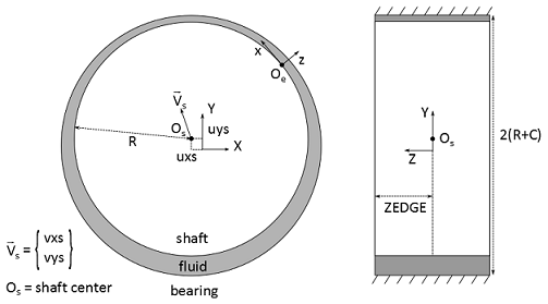
The element is defined by the real constants represented in Figure 218.2: FLUID218 Real Constants and listed in Table 218.1: FLUID218 Real Constants.
Table 218.1: FLUID218 Real Constants
| No. | Name | Description |
|---|---|---|
| 1 | C | Constant radial clearance. If zero, node-based radial clearance is used (CI to CL) |
| 2 | R | Radius of the shaft |
| 3 | UXS | Shaft center X location (static analysis only) |
| 4 | UYS | Shaft center Y location (static analysis only) |
| 5 | VXS | Shaft center X velocity (static analysis only) |
| 6 | VYS | Shaft center Y velocity (static analysis only) |
| 7 | ZEDGE | Z location of bearing edge. Used for moments calculation. |
| 8 | CI | Radial clearance at node I |
| 9 | CJ | Radial clearance at node J |
| 10 | CK | Radial clearance at node K |
| 11 | CL | Radial clearance at node L |
UXS, UYS, VXS, and VYS define the shaft center equilibrium position in the XY plane.
FLUID218 Output Data
The solution output associated with the element is in two forms:
Nodal degrees of freedom included in the overall nodal solution
Additional element output as shown in Table 218.2: FLUID218 Element Output Definitions
A general description of solution output is given in Table 218.2: FLUID218 Element Output Definitions. See the Basic Analysis Guide for ways to view results.
The Element Output Definitions table uses the following notation:
A colon (:) in the Name column indicates that the item can be accessed by the Component Name method (ETABLE, ESOL). The O column indicates the availability of the items in the file jobname.out. The R column indicates the availability of the items in the results file.
In either the O or R columns, “Y” indicates that the item is always available, a letter or number refers to a table footnote that describes when the item is conditionally available, and “-” indicates that the item is not available.
Table 218.2: FLUID218 Element Output Definitions
| Name | Definition | O | R |
|---|---|---|---|
| EL | Element number | Y | Y |
| NODES | Nodes - I, J, K, L | Y | Y |
| MAT | Material number | Y | Y |
| AREA | Area | Y | Y |
| XC, YC, ZC | Location where results are reported | Y | 1 |
| PG (x, y, z) | Fluid velocity at mid-thickness in element coordinate system | Y | Y |
| H | Fluid film thickness at nodes | Y | Y |
| HDOT | Fluid film thickness time derivative at nodes | Y | Y |
| HC | Fluid film thickness at centroid | Y | Y |
| PC | Fluid pressure at centroid | Y | Y |
| F (X, Y) | Forces (opposite to fluid forces acting on the shaft). Zero if pressure at centroid is negative. | Y | Y |
| M (X, Y) | Moments (opposite to fluid moments acting on the shaft). Zero if pressure at centroid is negative. | Y | Y |
| MUC | Dynamic viscosity at centroid | Y | Y |
| DENSC | Density at centroid | Y | Y |
| TEMPC | Temperature at centroid | Y | Y |
| VELC (T, TT, A) | Fluid velocities at mid-thickness at centroid: Tangential (squeeze term only), Total Tangential, Axial | Y | Y |
| TORQC (S, B, SA) | Shear torques at centroid: on Shaft, on Bearing, on Shaft with Adjustment (reduced to the squeeze term if the pressure is negative) | Y | Y |
Available only at centroid as a *GET item.
Table 218.3: FLUID218 Item and Sequence Numbers lists output available via ETABLE using the Sequence Number method. For more information, see The General Postprocessor (POST1) in the Basic Analysis Guide and The Item and Sequence Number Table in this reference. The following notation applies:
- Name
Output quantity as defined in Table 218.2: FLUID218 Element Output Definitions.
- Item
Predetermined Item label for ETABLE command.
- E
Sequence number for single-valued or constant element data.
- I, J, K, L
Sequence number for data at nodes I, J, K, L.
Table 218.3: FLUID218 Item and Sequence Numbers
| Output Quantity Name | ETABLE and ESOL Command Input | |||||
|---|---|---|---|---|---|---|
| Item | E | I | J | K | L | |
| H | NMISC | - | 1 | 2 | 3 | 4 |
| HDOT | NMISC | - | 5 | 6 | 7 | 8 |
| HC | NMISC | 9 | - | - | - | - |
| PC | NMISC | 10 | - | - | - | - |
| FX | NMISC | 11 | - | - | - | - |
| FY | NMISC | 12 | - | - | - | - |
| MX | NMISC | 13 | - | - | - | - |
| MY | NMISC | 14 | - | - | - | - |
| MUC | NMISC | 15 | - | - | - | - |
| DENSC | NMISC | 16 | - | - | - | - |
| TEMPC | NMISC | 17 | - | - | - | - |
| VEL-T | NMISC | 18 | - | - | - | - |
| VEL-TT | NMISC | 19 | - | - | - | - |
| VEL-A | NMISC | 20 | - | - | - | - |
| TORQC-S | NMISC | 21 | - | - | - | - |
| TORQC-B | NMISC | 22 | - | - | - | - |
| TORQC-SA | NMISC | 23 | - | - | - | - |
FLUID218 Assumptions and Restrictions
The bearing axis and the rotational velocity of the shaft must be along the global Z axis.
The fluid film thickness at a node is calculated based on the node location, the bearing clearance, and the shaft position. It must always be positive.
This element is based on the local coordinate system. Ensure that the element is oriented as described in "FLUID218 Input Data". (ESYS settings are ignored.)
Fluid velocity (PG) must be output in the element coordinate system (RSYS,SOLU). Consequently, output in any other coordinate system (for example, RSYS,0) is not supported, and vector display (PLVECT) is also not supported.
MU must be nonzero.
For problems involving variable viscosity (or density), the solution is nonlinear and may not converge easily if the parameters show large variations. The solution may also converge too soon due to a loose convergence criterion. Check results carefully.
To force more iterations, you can:
Specify a nonzero initial condition on pressure, which can be calculated with constant viscosity (or density). Ansys, Inc. recommends this option.
Tighten the convergence criteria (CNVTOL) using an estimated suitable tolerance.
Try both options simultaneously.
Node-based radial clearance definition is supported for the fluid-only element (KEYOPT(1) = 0).