Modeling general contact consists of the basic steps outlined below.
| Step | Task | Commands Used |
|---|---|---|
| 1 | Build the finite element model | Use typical modeling commands as described in the Modeling and Meshing Guide |
| 2 | Create rigid target surfaces (if needed) via mesh tools [1] | LMESH, AMESH |
| 3 | Generate general contact surfaces | GCGEN |
| 4 | Identify general contact surfaces where specific contact control is needed [1] | CM |
| 5 | Apply surface geometry corrections where needed [1] | SECTYPE, SECDATA |
| 6 | Define non-default contact settings [1] | KEYOPT |
| 7 | Define contact interactions or exclusions between specific surfaces [1] | GCDEF |
| 8 | Assign contact interface behavior [1] | MP, TB |
| 9 | Assign contact properties via real constants [1] | R, RMODIF |
In many cases, you only need to complete steps 1 and 3 in order to implement general contact in your analysis. The remaining steps are typically needed only if non-default interface behavior is required in some regions of the model.
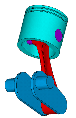
To demonstrate the simplicity of this procedure, general contact is defined for the four-piece piston assembly shown below.
For this example it is assumed that the finite element model is already in place and that the following two node components have been created. PIN contains exterior nodes on the cylindrical surface of the pin. ROD contains exterior nodes on the surface of the rod that can contact the pin.
The goal is to define bonded contact between the pin and the connecting rod, and no-separation sliding contact everywhere else. Following is a summary of the input required for the general contact definition.
/PREP7
! Build the finite model and create all base elements
! Create a node component PIN (exterior nodes on the cylindrical surface of the pin)
! Create a node component ROD (exterior nodes on the cylindrical surface of the rod)
!
GCGEN                                        ! Form general contact surfaces
SECTYPE,PIN,CONTACT,CYLINDER    ! Cylindrical geometry correction on pin
SECTDATA, …                                  ! Define the section data
SECTYPE,ROD,CONTACT,CYLINDER    ! Cylincrical geometry correction on rod
SECTDATA, …                                  ! Define the section data
GCDEF,AUTO,all,all,NoseID,RID1               ! Define default contact interaction
!
! NoseID is a specified material ID; RID1 is a specified real constant ID
!
TB,INTER,NoseID,,ANOSE         ! Specify interface behavior: ANOSE is no-separation always
RMOD,RID1…                     ! Specify contact control parameters

GCDEF,AUTO,PIN,ROD,BondID,RID2  ! Define a specific contact interaction
                                                            ! between the pin and rod
! BondID is a material ID, RID2 is a real constant ID
!
TB,INTER,BondID,,ABOND         ! Specify interface behavior: ABOND is bonded always


