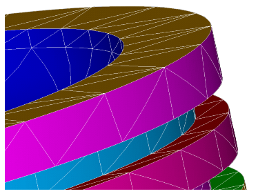
After building a complete finite element model and defining rigid target surfaces (if needed), the next step is to define general contact via the GCGEN command. This command automatically generates general contact surfaces and assigns section IDs to each surface based on physical parts and geometric shapes in the model. The general contact surfaces overlay the exterior faces of existing base elements, which can be 2D or 3D solid elements, 3D shell elements (top and bottom), 3D beam elements, or 2D shell elements (top and bottom).
Various settings on the GCGEN command allow you to control how the general contact surfaces are defined, as described in the following sections:
The general contact elements can be created, updated, removed, and selected using
the Option argument on the GCGEN
command. These options are described in the table below.
By default, GCGEN automatically defines contact surfaces on exterior faces of the base elements in the model. It creates surface contact elements for modeling surface-to-surface contact (CONTA172 for a 2D model, CONTA174 for a 3D model), and 3D line contact elements (CONTA177) for modeling 3D beam-to-beam contact and/or 3D beam-to-surface contact.
Note that the surface-to-surface contact elements (CONTA172 and CONTA174) generated by GCGEN are overlaid on the surfaces of both linear (lower-order) and quadratic (higher-order) solid and shell elements.
Elements created by GCGEN are identified by a zero real constant ID.
Options for Creating General Contact
(GCGEN,Option) | ||
Option
| Action | Comments |
| NEW | Create a new general contact definition | This option removes all existing general contact elements and
generates new elements with new section IDs. Any existing
GCDEF specifications,
SECTYPE / SECDATA general
contact data, and general contact element types are also removed. If
no general contact elements or data exist, this option behaves the
same as Option = UPDATE. |
| UPDATE | Create general contact elements on newly added (or selected) base elements | This is the default option. Use this option if your model contain
existing general contact elements and you wish to create additional
general contact elements on newly added (or selected) base elements.
The newly generated contact elements are assigned new section IDs.
Existing general contact elements remain with their previously
assigned section IDs and element attributes. Existing
GCDEF and SECTYPE /
SECDATA general contact data are respected.
If no general contact elements or data exist, this option behaves
the same as Option = NEW. |
| DELETE | Remove the general contact definition | This option completely removes the general contact definition, including all contact elements, existing GCDEF specifications, SECTYPE / SECDATA general contact data, and general contact element types. |
| SELECT | Select all general contact elements |
Use this option to select all contact and target elements in the general contact definition. (This option is valid only in PREP7.) ESEL,S,REAL,GCN is an alternative way to do the same selection. In this case, the component label GCN indicates that all contact and target elements used in a general contact definition (that is, elements identified by real constant ID = zero) are to be selected. (The ESEL command is valid in any processor.) |
By default, 3D beam-to-beam contact and 3D beam-to-surface contact are included under the general contact definition as long as any 3D beam elements are selected in the model. To exclude 3D beam-to-beam contact and 3D beam-to-surface contact, either unselect the beam elements before issuing GCGEN, or delete the CONTA177 general contact elements after the GCGEN command is issued.
When base elements involve existing interfaces that are connected by one of the following methods:
you need to either unselect those base elements on the interfaces before issuing the GCGEN command, or you need to delete the general contact elements created by GCGEN on those interfaces after the GCGEN command is issued.
In addition to surface-to-surface contact and beam-to-beam contact, the general contact definition can include 3D edge-to-surface and 3D edge-to-edge contact (CONTA177 elements), and 2D or 3D vertex-to-surface contact (CONTA175). CONTA177 line contact elements are added to solid body feature edges and shell body perimeter edges, and CONTA175 point elements are added to convex corners of solid and shell bodies and endpoints of beam structures. The purpose of adding these line and point elements is to avoid localized penetration of a feature's edge or corner into other surfaces and edges.
The EdgeKEY argument of the GCGEN
command enables you to control placement of the CONTA177
and CONTA175 elements. By default
(EdgeKEY = 0), no supplemental
CONTA177 or CONTA175 elements
are included. That is, 3D edge-to-surface, 3D edge-to-edge, and 3D vertex-to-surface
contact are not considered.
EdgeKEY
| Action |
|---|---|
| 0 | Exclude all edges and vertices (default) |
| 1 | Include feature edges only |
| 2 | Include shell perimeter edges only |
| 3 | Include both feature edges and shell perimeter edges |
| 4 | Include feature edges and vertices, shell perimeter edges and vertices, and beam vertices |
| 5 | Include feature vertices, shell perimeter vertices, and beam vertices |
GCGEN automatically assigns section IDs and element type IDs to
general contact surfaces. You can control how the IDs are assigned to the surfaces
by specifying the SplitKEY argument on the
GCGEN command.
SplitKEY
| Action |
|---|---|
| SPLIT | Assign a different section ID and contact element type ID for every geometric face of each physical part (default) |
| PART | Assign a different section ID and contact element type ID for every surface that covers a physical part |
Using SplitKEY = PART
When SplitKEY = PART, the
program assigns a unique section ID and contact element type ID for every surface
that covers a physical part. In other words, the program assigns different section
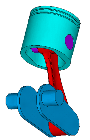
IDs and element type IDs to surfaces that are not connected (see the figure of the
piston model below). Compared to the SPLIT option, this option produces fewer unique
section IDs, which can make it easier to specify interface interactions via the
GCDEF command. The PART option is recommended for large
assemblies modeled with bonded contact.
In some cases, the surface geometry shapes vary across different regions of a
physical part, and it may be desirable to have a different section ID assigned to
each geometric surface. For instance, you may wish to apply a geometry correction
only on the cylindrical surface of a cylinder but not on the two circular ends. In
this case, you should set SplitKEY = SPLIT instead of
PART.
Using SplitKEY = SPLIT
When SplitKEY = SPLIT, the program assigns different
section IDs and contact element type IDs to each unconnected part, and also assigns
different IDs to every split face within each part and different section IDs to the
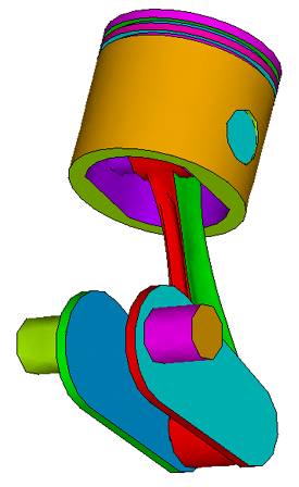
top and bottom surfaces of 2D shell and 3D shell bodies. Many more section IDs and
contact element type IDs are created as compared to the PART option, as shown in the
figure below. (See the discussion of split criteria in Feature Angle (FeatureANGLE)).
As the default option, the SPLIT logic gives you more flexibility for assigning interface interactions (GCDEF command) to different portions of the model that might come into contact. Note that a geometry correction can be applied directly on a split face of a physical part.
The FeatureANGLE argument on the
GCGEN command is an angle tolerance used for determining
feature edges (EdgeKEY) and general surfaces
(SplitKey).
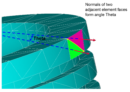
The exterior facets of the selected base solid and shell elements are divided into subsets based on the angle between the normals of neighboring faces (see Theta in Figure 8.4: Angle Between Normals of Adjacent Element Faces). On a flat or smooth surface as shown in this figure, adjacent exterior element faces have normals that are parallel or nearly parallel. That is, the angle between the adjacent normals is near zero degrees.
When the angle Theta between the normals of two adjacent faces is greater than
FeatureANGLE, the two faces are considered to be on
two separate surfaces (SplitKey = SPLIT). The edge
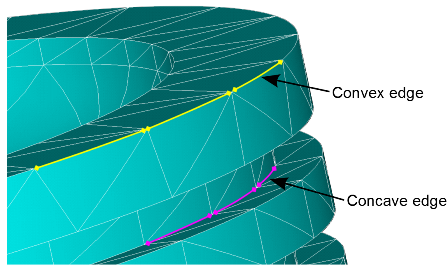
between the faces may be convex or concave (see Figure 8.5: Convex and Concave Edges). A
convex (or outside) edge is considered to be a feature edge and may be affected by
the EdgeKEY setting.
The edge/split calculation accounts for the curvature of high-order base elements,
which typically have an angle near zero degrees between facets, even for a coarse
mesh on a curved surface. As long as the base elements include midside nodes that
follow the curved surfaces, you should not have to use a larger value of
FeatureANGLE to properly subdivide surfaces on
coarsely meshed, curved objects.
Figure 8.6: General Contact Surfaces Created by Using Default GCGEN Settings shows the resulting general contact surfaces for the
example model when GCGEN is issued with default settings
(FeatureANGLE = 42,
EdgeKEY = 0, SplitKey =
SPLIT). Each general contact surface is identified by a unique section ID. This is
illustrated in the figure by different colors representing different section IDs for
surfaces determined as a result of the SPLIT option.
A FeatureANGLE value that is too small can cause the
inclusion of unwanted feature edges, or cause extraneous splitting on continuous
surfaces. A FeatureANGLE value that is too large can
cause the omission of needed feature edges (EdgeKEY), or
cause independent portions of the base model exterior to be lumped together as a
single general surface (SplitKey). Any of these
situations can reduce accuracy or efficiency of the general contact solution.
You should plot and verify edge contact elements (created via
EdgeKEY) and section IDs of the new general contact
elements after issuing GCGEN.
You can control which base elements are considered for the general contact
generation by specifying the selection key (SelOpt) on
the GCGEN command:
SelOpt
| Action |
|---|---|
| ATTACH | Use a recursive adjacency selection to obtain complete physical parts, starting from the selected base elements, before generating general contact elements (default). |
| SELECT | Use only the initially selected base elements to generate general contact elements. |
The SelOpt = SELECT option creates general contact
elements overlaid on the free faces of selected base elements. Element faces are
determined from the selected nodes. All nodes on the face must be selected for the
face to be used. The operation is similar to that used for generating contact
elements via the ESURF command. This option is useful for
splitting a smooth general contact surface into several sub-surfaces when different
sub-surfaces have different interface behaviors.
The SelOpt = ATTACH option is used to create general
contact surfaces for the entire model. It is usually issued after all specific
general contact surfaces are created via the SelOpt =
SELECT option. The newly generated general contact surfaces will not overlap with
the existing surfaces when Option = UPDATE (default) on
the GCGEN command.
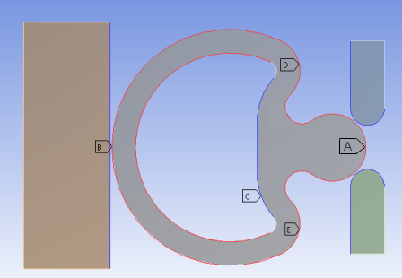
As an example, consider the model shown below in which a rubber seal is being pushed from the left by a block so that the seal’s bulb passes through the fixed channel on the right. Frictional contact interactions A, D, & E are defined with the Lagrange contact algorithm (KEYOPT(2) = 3). The friction coefficient applied to A is 0.2 and to D and E is 0.1
The example input below assumes that node components exist for surfaces A, D, and E as labeled in the figure.
/prep7

mp,mu,100,.1
mp,mu,110,.2
tb,inter,120,,,rough
tb,inter,130,,,standard


cmsel,s,bulb_node      ! Select node component for surface A
elsn
gcgen,,,,,select        ! Create general contact surface at surface A
cmsel,s,upperShoulder  ! Select node component for surface D
esln
gcgen,,,,,select        ! Create general contact surface at surface D
cmsel,s,lowerShoulder  ! Select node component for surface E
esln
gcgen,,,,,select        ! Create general contact surface at surface E
allsel,all
keyopt,gcn,2,3         ! Define Lagrange multiplier method for A, D, E
gcgen                  ! Generate the rest of the general contact surfaces


gcdef,auto,all,all,130
gcdef,symm,all,self,120
gcdef,asym,outeredge_node,leftblock_node,120
gcdef,asym,bulb_node,channel_node,110
gcdef,asym,upperShoulder,channel_node,100
gcdef,asym,lowerShoulder,channel_node,100


