The use of section ID numbers to identify general contact surfaces plays an important role in the general contact framework. The GCDEF command, which defines contact interactions between specific surfaces, accepts section IDs for the surfaces involved. Geometry corrections that you can apply to certain contact surfaces via SECTYPE and SECDATA commands also rely on section IDs to identify the affected surfaces. Similarly, element type IDs play a roll when defining non-default contact properties via the KEYOPT command.
When many parts exist in a finite element model, determining a specific section ID or element type ID can be difficult. To circumvent this problem, the GCDEF, SECTYPE, and KEYOPT commands can accept node component names as input in place of section IDs. Thus, you do not necessarily need to know section and element type ID numbers in order to manage general contact interactions between surfaces.
The section IDs that identify general contact surfaces and the element type IDs that identify general contact element types are assigned automatically during execution of the GCGEN command. You can list the section IDs and element type IDs for general contact elements by issuing the ELIST command. The IDs can also be displayed on an element plot (EPLOT command) by turning on the section number or element type display key (/PNUM,SECT,1 or /PNUM,TYPE,1).
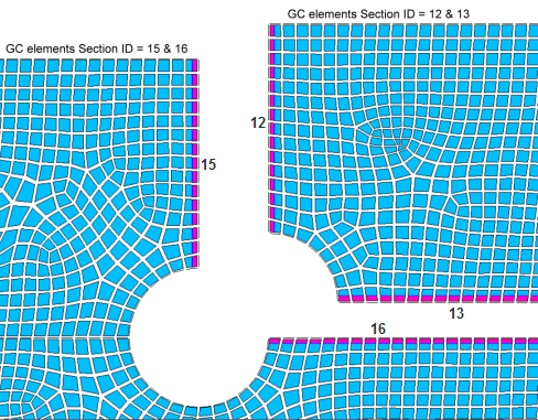
The example below demonstrates a 2D model having four general contact surfaces that may interact. The GCGEN command created general contact elements on the surfaces and assigned a unique section ID to each surface as shown in the figure.
Assume that material ID = 5 (which defines a particular contact behavior) should be assigned to the contact interactions. In this case, you would issue the following GCDEF commands to assign the properties for all possible contact interactions (see Defining Contact Interactions (GCDEF Command) for command details):
GCDEF,,15,12,5
GCDEF,,15,13,5
GCDEF,,16,12,5
GCDEF,,16,13,5
For this simple model, it was easy to identify the section IDs associated with the surfaces of interest, and the above commands are valid input.
There are several drawbacks to using section IDs to identify general contact surfaces on commands such as GCDEF. First, there is no way to predict the section IDs for the surfaces involved until after the GCGEN command is issued. You must list or plot the elements after GCGEN to determine the section IDs. Another concern is that reusing the same input with a modified mesh could produce different section IDs. Reusing the same input in a later release of Mechanical APDL might also result in different section IDs. In these situations, the input might create invalid GCDEF specifications.
To avoid these issues, it is good practice to define node components (CM command) on each of the surfaces where you may need to define non-default general contact interactions. When creating the node components, use select logic based on spatial location, or reference the underlying solid model (or CAD model) and select the attached nodes. This will minimize the effect of remeshing on the node component definition. Each node component may contain one or more than one general contact attribute (section ID or element type ID). You can then reference those node components on the GCDEF, SECTYPE, and KEYOPT commands instead of inputting section IDs.
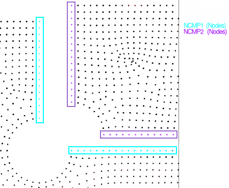
Continuing with our 2D example, the figure below shows node components NCMP1 and NCMP2 that contain nodes on the surfaces that might come into contact. Note that both node components encompass more than one surface.
The component names can be input instead of section IDs on the GCDEF command:
GCDEF,,NCMP1,NCMP2,5
The GCDEF command loops through all valid section IDs found in each node component and creates general contact interactions for all possible surface combinations. As a result, the input was greatly simplified by using node components.
Use of component names is especially convenient when writing a batch input file or macro for defining general contact, or a command snippet for use in Ansys Workbench. (Ansys Workbench creates node components automatically wherever you define a named selection on the geometry.)
The output echo of the GCDEF, SECTYPE, and KEYOPT commands show the general contact section IDs or type IDs referenced by the given node components (sections 12, 13, 15, and 16 in this example). This is how the command information is stored and listed. Keep in mind that downstream changes to the nodal components cannot change what is already defined by one of these commands.
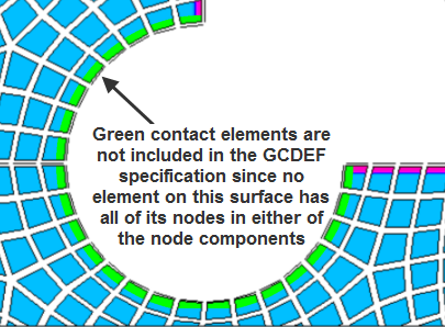
For a section ID (or element type ID) of a particular surface to be considered, all nodes (including midside nodes, if any) of at least one contact element on that surface must be included in the node component. In this example, the contact elements on the circular arc (shown in green on the figure below) are not included in the GCDEF specification because no element on that surface has all of its nodes included in either of the node components.
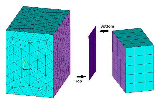
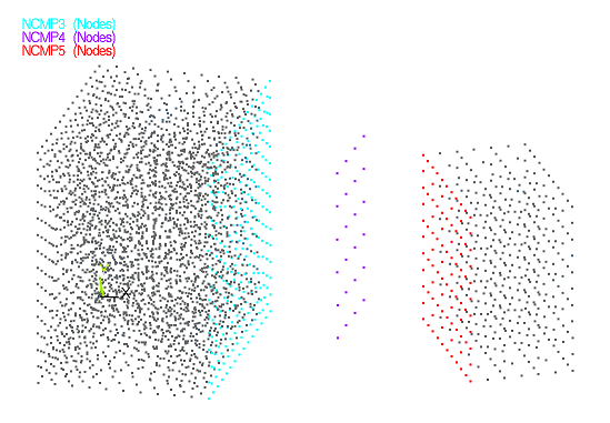
Next, consider two 3D solid bodies separated by a shell body, all of which can possibly contact each other at the shaded locations (see figure below).
Suppose the shell has different surface characteristics on each side. Perhaps the top (TOP) is slick but the bottom (BOT) is coated with a quick-bonding, super-strength adhesive. In this case, two different material ID numbers are needed for the general contact interactions involving the two shell sides (assume material 5 at the shell top and material 6 at the shell bottom).
Note that orientation of the shell elements is controlled by the element node order (counterclockwise when viewed from the TOP side). It is important that you know which side is the top and which side is the bottom when defining general contact interactions for shell elements.
The first step is to establish nodal components for each of the 3 surfaces (the shell is one surface that has a top and a bottom). The node component names are NCMP3, NCMP4, and NCMP5.
For shell elements, you can add the extension _TOP or _BOT to the component name entered on the GCDEF command to indicate whether section IDs from the top or bottom surface will be considered.
The following command assigns material ID 5 to the general contact interaction between the left block and the top of the shell:
GCDEF,,NCMP3,NCMP4_TOP,5
In a similar manner, material number 6 is assigned to the general contact interaction between the shell bottom and the right block:
GCDEF,,NCMP4_BOT,NCMP5,6
Finally, the following command is issued to account for possible interactions between the two solid blocks. Material 7 is assumed for this interaction:
GCDEF,,NCMP3,NCMP5,7
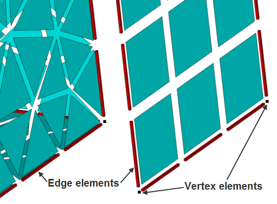
Depending upon the base element types and the options you use on GCGEN, you may have face, edge, and vertex general contact elements on or around a surface. Ordinarily, all three types of general contact elements are addressed by the nodal component input options. However, you can isolate one type with the _FACE, _EDGE, and _VERT component name extensions, which operate the same as the _TOP and _BOT extensions. See Specifying General Contact Interactions Between Nodal Components for more information.
Continuing with the same example, assume that the command
GCGEN,,,4 (where EdgeKEY = 4) was
used to generate the general contact. In this case, the model also includes
CONTA177 edge elements and
CONTA175 vertex elements in the general contact
definition, as shown in the zoomed in figure below. The NCMP3 node component surface
is on the left, and the NCMP4 node component surface (the shell element surface) is
on the right.
Consider the following GCDEF specification involving node components NCMP3 and NCMP4:
GCDEF,,NCMP3,NCMP4,14
This specification between the left block surface (NCMP3) and the top of the shell (NCMP4) applies to all face, edge, and vertex general contact elements on those surfaces.
You could separately call out face, edge, or vertex general contact elements in any desired specification:
GCDEF,,NCMP3_FACE,NCMP4_TOP,15
GCDEF,,NCMP3_EDGE,NCMP4_BOT,16
GCDEF,,NCMP3_VERT,NCMP4_FACE,17
You could also specify how surface general contact elements (CONTA174 in this example) interact with CONTA175 vertex general contact elements throughout the entire model:
GCDEF,,ALL_VERT,ALL_FACE,27


