After a part is built, it is common to heat treat it to relieve residual stresses. Heat treating is a process using the controlled application of heat to alter the physical and chemical properties of a material. In an annealing process, metal is heated in a furnace to a particular high temperature, held there for a long time (hours or days) and then allowed to cool slowly. This may be done either before or after removing the part from the base plate. These scenarios can be simulated in Mechanical.
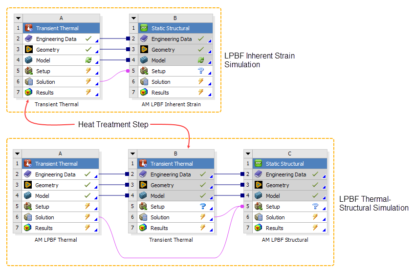
To model the heat treatment process, an additional Transient Thermal analysis is required. The data flow at the system level in Workbench is depicted in the figure below for both Inherent Strain and Thermal-Structural simulations. The workflow systems depict how data flows from one type of analysis to another. For example, temperatures from the two (uncoupled) thermal analyses are required as inputs for the structural analysis in the Thermal-Structural simulation. The proper time sequence—or when that data is used—is defined in the AM Process Sequence worksheet.
You can account for the stress relief mechanism in a heat treatment analysis in one of two ways:
By using a creep model in Workbench's Engineering Data. This approach results in a more realistic stress relaxation curve as shown in an equivalent stress plot.
Note: The creep models for Ansys predefined AM materials are not applicable for DED or sintering simulations.
By specifying a Relaxation Temperature in the Static Structural analysis settings. This is a simplified approach resulting in an abrupt stress relaxation.
The following topics related to heat treatment are available:
- 6.8.1. Overview of Heat Treatment Workflow
- 6.8.2. Define Engineering Data - Unsuppress Creep Properties
- 6.8.3. Add Transient Thermal System to the Project
- 6.8.4. Define AM Process Steps - Add Base Unbolting and Heat Treatment Steps to the Sequencer
- 6.8.5. Establish Analysis Settings - Define Creep Relaxation Temperature
- 6.8.6. Apply Boundary Conditions - Add Convection for Heat Treatment Step
- 6.8.7. Solve the Simulation - Check Units First!
- 6.8.8. Heat Treatment Examples
The LPBF Setup Wizard includes heat treatment modeling as an option. We strongly advise you to use the wizard to set up your simulation because it automates much of the tedious set-up, including enabling the creep model, applying boundary conditions, and adjusting the unit system during solution when you choose to simulate with creep effects. If you do not use the wizard, follow these steps to simulate heat treatment after the build:
| Heat Treatment Workflow at a Glance (Non-Wizard Workflow) | |
|---|---|
| Simulation Step | Considerations for Simulating Heat Treatment |
| 1. Create analysis system | Set up an LPBF simulation, either Inherent Strain or Thermal-Structural. |
| 2. Define Engineering Data | If simulating heat treatment using a creep model as the mechanism for stress relief, identify it here in Engineering Data. For Ansys predefined AM materials, open Engineering Data, select the desired material, and unsuppress the creep model (either Norton or Generalized Garofalo). Take note of the unit system used to define the creep model. |
| 3. Attach geometry and launch Mechanical | No special considerations. |
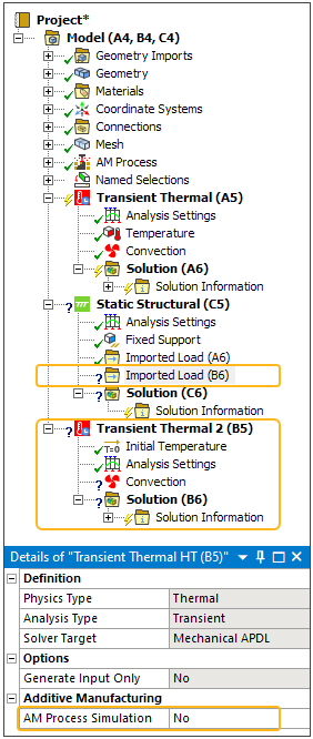
| 4. Add Transient Thermal system for heat treatment step | In Mechanical, add a Transient Thermal system to the project for the heat treatment step. Be sure AM Process Simulation is set to No for the new system. Insert an Imported Load into the Static Structural system. |
| 5. Identify geometry | No special considerations. |
| 6. Assign materials | No special considerations. |
| 7. Apply mesh controls and generate mesh | No special considerations. |
| 8. Identify and/or generate supports | No special considerations. |
| 9. Define connections | No special considerations. |
| 10. Define AM process steps | Using the Sequencer, add a base unbolting step first, followed by a heat treatment step. |
| 11. Define build settings | No special considerations. |
| 12. Establish analysis settings | If simulating heat treatment using a relaxation temperature as the mechanism for stress relief, set it here in Static Structural > Analysis Settings. |
| 13. Apply boundary conditions | In addition to the usual boundary conditions for an LPBF simulation, apply convection to the surfaces of the part, supports, and base plate for the heat treatment step. For the Imported Load, specify the Transfer Step to be Heat Treatment Step. |
| 14. Solve the simulation | If simulating with creep properties, switch to the unit system used in the creep model before solving. |
| 15. Review results | Add an Equivalent Stress result scoped to the build to see the stress relief. Add an Equivalent Creep Strain result to see the creep accumulation. |
When simulating with heat treatment, use either creep properties or a relaxation temperature as the mechanism for stress relief, but not both.
To use creep properties as the mechanism for stress relief, unsuppress the creep model in Engineering Data. (By default, creep properties are suppressed, meaning creep effects are ignored.) Unsuppress the creep model as follows:
In Workbench, double-click the Engineering Data cell in the first (left-most) system. This opens the Engineering Data tab and workspace
Click your choice of materials from the list of available AM materials shown. In this example, we've chosen 316 Stainless Steel. Notice the Source column (column D) shows Additive Manufacturing Materials.
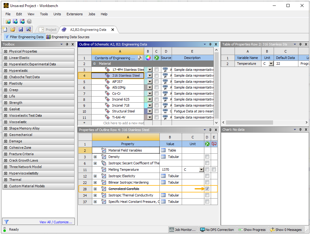
Clear the check box to the right of the creep model so that the creep properties are unsuppressed. In this example, the model is Generalized Garofalo. The model may also be Norton, depending on your chosen material. Expand the model cell to view the creep constants and reference units. In this example, the reference unit system is in millimeters.
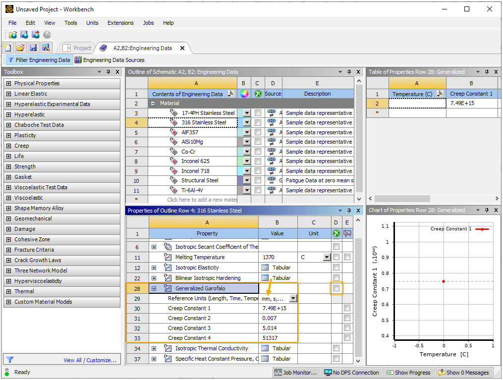
Important: Take note of the reference unit system used to define the creep model. It may be defined in meters or millimeters. The unit system used during solution must be the same unit system used to define the creep model. You may set up your simulation and review results in any unit system but be sure to switch to the creep model system just before you initiate the solve. Should you forget to do this, you will see the following error message and the simulation will not solve. "An error occurred inside the SOLVER module: The "Reference Units" defined for the Creep material property does not match the solver unit system." If you see this error, clear generated data, change to the creep unit system, and solve again.
Click the Project tab at the top of the Workbench window to go back to the system view.
What if I forget to unsuppress the creep model?
If you forgot to unsuppress the creep model in Engineering Data and you have already assigned material properties to the bodies in Mechanical, you must update the project after unsuppressing the creep model. Unsuppress the creep model as described above, and then in Workbench system view, right-click the Model cell in the first Transient Thermal analysis and select Update before returning to Mechanical.
Add the Transient Thermal system to account for heat treatment as follows:
In Mechanical, from the Home tab, click the Analysis button to reveal a drop-down list of analysis types. Select the Transient Thermal system.
Click the new Transient Thermal object in the project tree and in the Details view, under Additive Manufacturing, change the AM Process Simulation setting to No. (This option may already be set to No, depending on the LPBF system you set up.)
Right-click the Static Structural object and select Import Load > Transient Thermal. This adds a new Imported Load object under the structural system. You will need to go back to this object later after the AM process steps are defined.
When modeling heat treatment, it is best to also include a base unbolting step, in which the constraints for UX, UY, and UZ are removed from the base plate nodes. This eliminates any artificial tension in the base caused by fixed boundary conditions and thermal expansion during heating, which would otherwise occur if base unbolting is not used.
Add base unbolting and heat treatment steps to the AM Process Sequence worksheet as follows:
Select the AM Process object and then click the Sequence button (AM Process group) on the context toolbar. The sequencer worksheet comes up.
Click Add Step on the Static Structural side of the sequencer worksheet and select Base Unbolt to add the unbolting step first. Click Add Step again and select Heat Treatment Step.
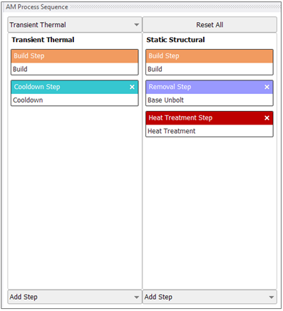
Select the Static Structural object in the project tree and then select the Imported Load object underneath it that belongs to the new heat treatment Transient Thermal system. In the Details view, under Additive Manufacturing, change the Transfer Step option to the new Heat Treatment Step. This ensures the thermal data from the heat treatment step is transferred at the correct time (load step).
When simulating with heat treatment, use either creep properties or a relaxation temperature as the mechanism for stress relief, but not both.
To use a relaxation temperature as the mechanism for stress relief, click Analysis Settings under the Static Structural object. In the Details view, under Additive Manufacturing Controls, change the step to heat treatment step, then change Relaxation Temperature to User Specified and then change the Value to your desired stress relaxation temperature for the material.
In addition to the typical boundary conditions for an LPBF simulation, apply convection to the surfaces of the part, supports, and base plate for the heat treatment step, as follows:
Right-click the Transient Thermal object corresponding to the heat treatment step and then select Insert > Convection.
Select all the bodies including the base plate (geometry selection) and hit Apply in the Details view. Are STL Supports automatically selected and included in body count?
In Details under Definition, Film Coefficient, enter a value for the convection coefficient of the gas in the furnace, or select Tabular Data.
Under Ambient Temperature, select Tabular Data.
In the Tabular Data area of the interface, specify the appropriate convection coefficient and temperature at different time points.
In Analysis Settings, change the Step End Time to match the final time in the convection tabular data. More details on how to control the time stepping settings are available here.
If simulating with creep properties, switch to the unit system used in the creep model before solving. Should you forget to do this, you will see the following error message and the simulation will not solve. "An error occurred inside the SOLVER module: The "Reference Units" defined for the Creep material property does not match the solver unit system." If you see this error, clear generated data, change to the creep unit system, and solve again.
Note that you can switch back to your preferred unit system for reviewing results after the solution is finished.
The following examples are available:
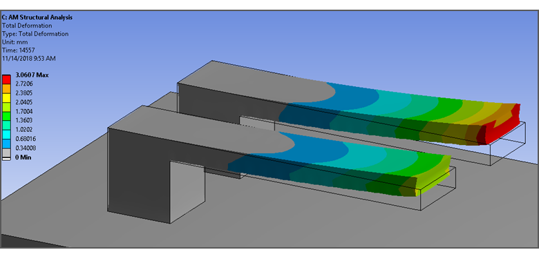
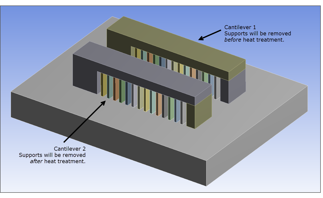
The following heat treatment project was set up to show the effects that heat treatment can have on stress and distortion in an additively manufactured part. Two cantilevers with supports are set up in the same additive manufacturing simulation with cutoff from the supports occurring at different time points for each cantilever. The first cantilever is removed from supports before heat treatment, and the second cantilever is removed after heat treatment.
To model this, the AM sequencer was set up as shown in the following figure.
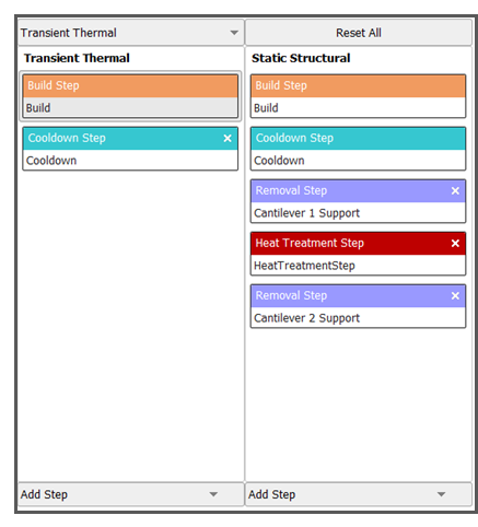
After simulating the additive manufacturing process and steps defined in the sequencer, the two cantilevers are left with different distortion magnitudes. The heat treatment step relieved residual stresses and led to decreased distortion in the second cantilever (on the left) after the cutoff step.