


The Materials database is only editable within ACP in Stand Alone mode. Otherwise, it draws all material properties from Engineering Data within Workbench. In this case, the material properties can be viewed- but not altered- in ACP.
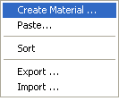
The context menu of the Materials class has the following options:
Create Material (Stand Alone only): Open a Material Properties dialog for creating a new material.
Paste (Stand Alone only): Paste a copied material into the material database.
Sort: Sort the list of materials alphabetically.
Export: Export the material database into a .csv file, ESAComp XML file, or an Ansys Workbench XML file.
Import (Stand Alone only): Import materials from a .csv file or ESAComp XML file.
More information on the import and export of ESAComp XML file can be found in ESAComp. Stackups and Sublaminates can also be exported to an ESAComp XML file format but are converted to laminates in the process.
Engineering constants, density, fabric fiber angle, as well as stress and strain limits, can be set to depend on scalar field variables, including Temperature, Shear Angle, and Degradation Factor. Other properties can only depend on temperature. The material properties are always shown at the reference point in the Materials object. Variable material data can be edited in Workbench Engineering Data.
In ACP, variable material data are considered in ACP-Post when evaluating failure criteria. Temperature-dependence comes into effect if the solution contains a temperature data block. Shearing of plies is considered if the material is dependent on the Shear Angle variable and at least one ply is draped. All other dependencies require the respective field variable to be defined by means of Look-Up Tables. For more information, see Variable Material Data in Composite Analyses and Analysis Using Variable Material Data.
Within the Workbench workflow, variable data are passed to and from ACP. In Stand-Alone mode, temperature-dependent data are passed to and from ACP if the import and export is in an Ansys file format, such as .CDB.
General variable material properties are read only from the Workbench Engineering Data (.ENGD) file. Export and import of material data within the Materials object via .csv or .XML file formats do not support general variable material data.
Here is the Material Properties dialog.
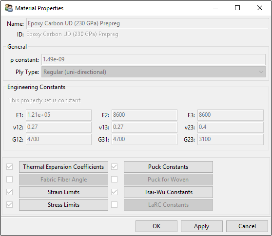
In the Material Properties dialog, the following preprocessing data is required:
Name: Name of the material.
ρ: Density of the material.
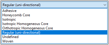
Ply Type: Defines the material type and controls which failure criteria evaluates the safety of a certain material (see Failure Criteria vs. Ply Type Table). Depending on the extrusion method (e.g. sandwich-wise extrusion) in the Solid Model, it also affects the volume mesh of the solid model .
Adhesive: Materials of this type are post-processed with specific failure criteria. An adhesive has isotropic mechanical properties.
Honeycomb Core: Sandwich core material with a honeycomb pattern.
Isotropic: Isotropic material and post-processed with the von Mises criterion.
Isotropic Homogeneous Core: Sandwich core material, such as foam, with isotropic elasticity. Note that orthotropic strength limits have to be defined for post-processing (failure criteria evaluation).
Orthotropic Homogeneous Core: Sandwich core material, such as balsa, with an orthotropic material characteristic.
Regular (uni-directional): Uni-directional reinforced material.
Undefined: If the material type is not known or not defined, then the ply type becomes undefined. This material type is not post-processed.
Woven: Weave material.
Orthotropic Young's Modulus:
E1: In-plane, in fiber direction (fiber direction is corresponding to angle 0 for the ply's definition)
E2: In-plane, orthogonal to fiber direction
E3: Out of plane direction
Orthotropic Poisson's Ratio:
ν12: In-plane
ν13: Out of plane, in fiber direction
ν23: Out of plane, normal to fiber direction
Orthotropic Shear Modulus:
G12: In-plane
G13: Out of plane, in fiber direction
G23: Out of plane, normal to fiber direction
Further failure properties can be activated. Depending on the Ply Type some properties are deactivated automatically.
Note: Engineering Data can only be modified in preprocessing. Once postprocessing has been initiated the data is frozen.
For thermal stress analyses, the thermal expansion coefficients of the material and the reference temperature must be given:
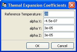
Reference Temperature: Temperature at which strain in the design does not result from thermal expansion or contraction
alpha X: In-plane, in fiber direction (fiber direction is corresponding to angle 0 for the ply's definition)
alpha Y: In-plane, orthogonal to fiber direction
alpha Z: Out of plane direction
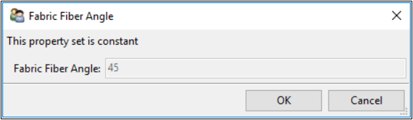
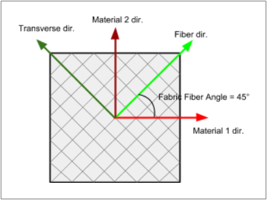
The Fabric Fiber Angle represents the angle between the Material 1 Direction and the Draped Fiber Direction. When no draping is specified, the Draped Fiber Direction coincides with the Fiber Direction. By default, the Fabric Fiber Angle is set to zero so that the Material 1 Direction coincides with the (draped) fiber direction.
When the Fabric Fiber Angle property is active and nonzero, you need to specify the Material Properties, Thermal Expansion Coefficients, Strain Limits and Stress Limits with respect to the material directions rather than the fiber directions. For instance, E1 and E2 would represent the Young’s moduli in the material 1 and 2 directions, respectively. However, the fiber direction is still the nominal modeling direction in ACP. For more information, see the Shear Dependent Materials in Composite Analysis example and the Material Designer User's Guide.
You can highlight the effect of the Fabric Fiber Angle by plotting the draped fiber direction and the material 1 direction of a selected analysis ply (see Draping).
The Strain Limits are used to calculate the IRF if the Max Strain criteria is selected in the failure criteria definition. Compressive strain limits must be negative.
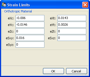
For orthotropic materials, 9 strain limits (5 in-plane and 4 out-of-plane strains) can be entered:
eXc: Normal strain, in-plane, in fiber direction, compression limit
eXt: Normal strain, in-plane, in fiber direction, tension limit
eYc: Normal strain, in-plane, orthogonal to fiber direction, compression limit
eYt: Normal strain, in-plane, orthogonal to fiber direction, tension limit
eZc: Normal strain, out of plane, compression limit
eZt: Normal strain, out of plane, tension limit
eSxy: In-plane shear strain
eSxz: Transverse (interlaminar) shear strain, plane in fiber direction
eSyz: Transverse (interlaminar) shear strain, plane normal to fiber direction
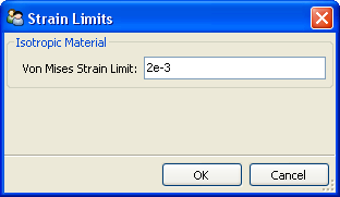
If the material is defined as isotropic, the von Mises Strain Limit can be entered:
All the other Failure Criteria definitions are based on values defined in the Stress Limits dialog. Compressive stress limits must be negative.
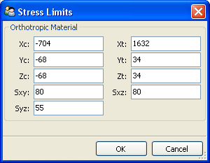
For orthotropic materials, 9 stress limits (5 in-plane and 4 out-of-plane strains) can be entered:
Xc: Normal stress, in-plane, in fiber direction, compression limit
Xt: Normal stress, in-plane, in fiber direction, tension limit
Yc: Normal stress, in-plane, orthogonal to fiber direction, compression limit
Yt: Normal stress, in-plane, orthogonal to fiber direction, tension limit
Zc: Normal stress, out of plane, compression limit
Zt: Normal stress, out of plane, tension limit
Sxy: In-plane stress strain
Sxz: Transverse (interlaminar) shear stress, plane in fiber direction
Syz: Transverse (interlaminar) shear stress, plane normal to fiber direction
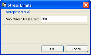
If the material is defined as isotropic the von Mises Stress Limit can be entered (equivalent to Tensile Yield Strength in Engineering Data):
The Puck failure criterion requires internal parameters, which depend on the material. The Material Classification drop-down menu offers a selection of pre-defined constants and also allows for the definition of custom constants. The menu has the following options:
Carbon: Sets pre-defined Puck constants for carbon fiber materials.
Glass: Sets pre-defined Puck constants for glass fiber materials.
Material-specific: Allows you to set your own Puck constants.
Ignore Puck Criterion: No constants are set.
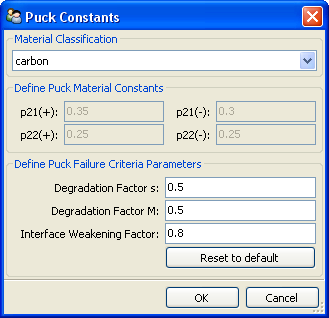
p21(+): Tensile inclination XZ
p21(-): Compressive inclination XZ
p22(+): Tensile inclination YZ
p22(-): Compressive inclination YZ
s and M: Degradation parameters
Interface Weakening Factor: Scales the interlaminar normal strength
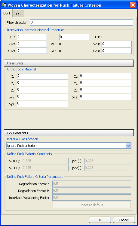
ACP’s Puck for Woven functionality allows you to evaluate the Puck failure criterion for woven materials. You specify two UD plies to represent the woven ply. During the failure evaluation, ACP evaluates the stresses for theses plies in the new material directions and computes the Puck failures. The relative ply angles, engineering constants, stress limits, and Puck constants must be defined for both plies.
This approach, proposed by Puck, has been validated by experiments. Warp dominated woven fabrics have yielded good results. Puck described that fabrics with similar amounts of reinforcement in the warp and weft direction (50%/50%)– and therefore having higher fiber undulation– need additional material characterization.
An alternative to Puck for Woven is the Maximum Stress Criterion. It does not require additional material properties (or characterization), and it has been successfully applied in different commercial projects.
Note: This specification does not affect the analysis model and is only considered in the failure analysis for the Puck criterion.
The Tsai-Wu constants are constants used into the interaction coefficient of the quadratic failure criteria for Tsai-Wu formulation. Refer to Tsai-Wu Failure Criterion for more details.
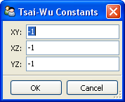
In ACP the Tsai-Wu constants correspond to:
2 F12 = XY, default -1
2 F13 = XZ, default -1
2 F23 = YZ, default -1
The LaRC failure criteria requires the following parameters to evaluate the failure in matrix and fiber:
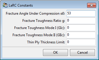
Fracture Angle Under Compression: The value for α0 used in the LaRC fiber and matrix failure. Default value is 53°.
Fracture Toughness Ratio: The ratio of the mode I to mode II fracture toughness, which is used in the fiber failure criteria.
Fracture Toughness Mode I
Fracture Toughness Mode II
Thin Ply Thickness Limit (set to 0.7 mm in Workbench mode)
For more information, see LaRC03/LaRC04 Constants.