This example demonstrates a possible workflow for composite analyses using homogenized material data (with shear dependency) for a woven composite provided by Material Designer. To this end, a simple model consisting of an inflated half-sphere is considered. The effect of ACP draping simulation combined with shear-dependent material properties will be shown.
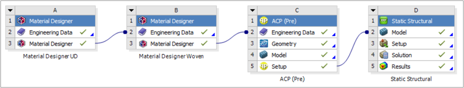
The following figure shows the Workbench setup. The material data of a Carbon/Epoxy woven fabric are computed by Material Designer (systems A and B) as illustrated in the Material Designer Woven Composite Tutorial. The composite lay-up and draping options are defined in ACP-Pre (system C). Finally, the structural effect of an internal pressure load is analyzed in system D (Static Structural).
If desired, you can download the model used in this example analysis and perform the steps yourself.
Homogenized Material Data
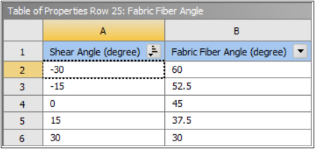
Following the Material Designer Woven Composite Tutorial, we generate homogenized material data for a Carbon/Epoxy woven fabric. In particular, we use an RVE whose material directions are aligned with the yarns bisectors, so that the resulting homogenized material remains orthotropic in presence of shear (see Fabric Fiber Angle in the Material Designer User's Guide).
We set up two analyses in Material Designer (Cell B in the Workbench project): a constant material analysis and a variable one with a shear angle between -30° and 30° as parameter. The resulting materials are then transferred to the Engineering Data component of the ACP system.
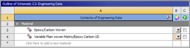
Note that the constant material has a constant Fabric Fiber Angle equal to 45°, while the variable material has a shear dependent Fabric Fiber Angle.
Fibers and Material 1 Directions in ACP
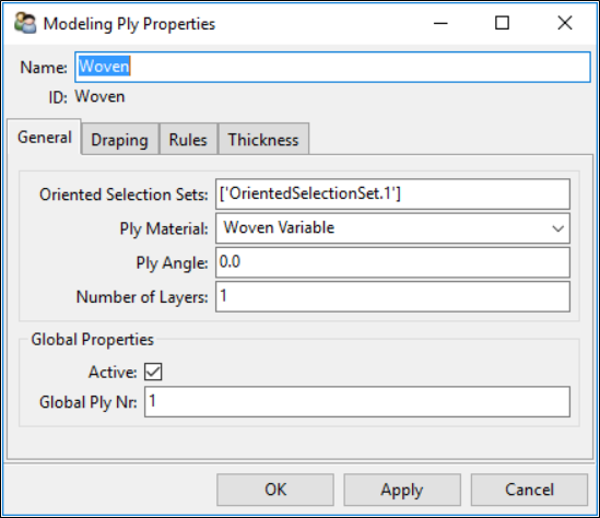
In ACP, we define a ply with a variable woven fabric and a ply angle of 0°.
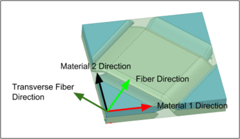
The effect of the Fabric Fiber Angle property can be highlighted by comparing the ply fiber directions with the material 1 direction.
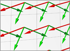
The material 1 direction identifies the direction in which the material properties are specified. However, the fiber direction is still the nominal modeling direction in ACP, that is, the Ply Angle still defines the orientation of the fibers with respect to the reference direction.
Draping
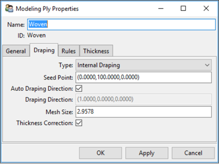
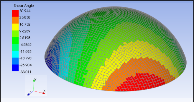
The Shear Angle can be defined as a result of ACP draping simulation (see Draping).
You can enable the Internal Draping algorithm in the Draping tab of the Modeling Ply Properties dialog.
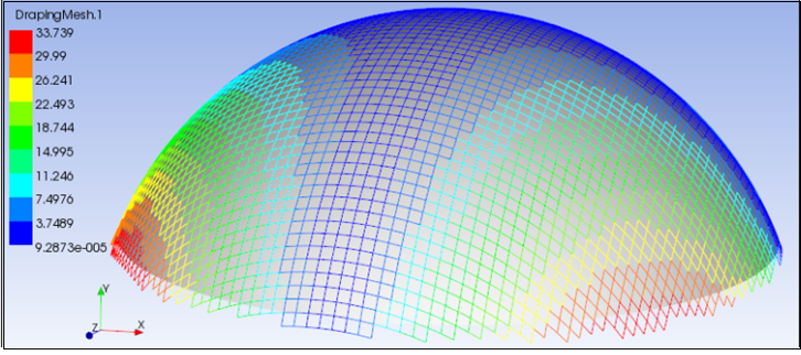
You can plot the local ply shear value due to draping using an Angle Plot with Draped Shear Angle as component.
In addition, you can further investigate the shearing effect due to draping by plotting the draped fiber and transverse directions, as well as the material 1 direction.
Figure 4.51: Draped Fiber Direction (Light Blue), Draped Transverse Direction (Blue) and Material 1 Direction (Red)

Plot of Shear Dependent Material Properties
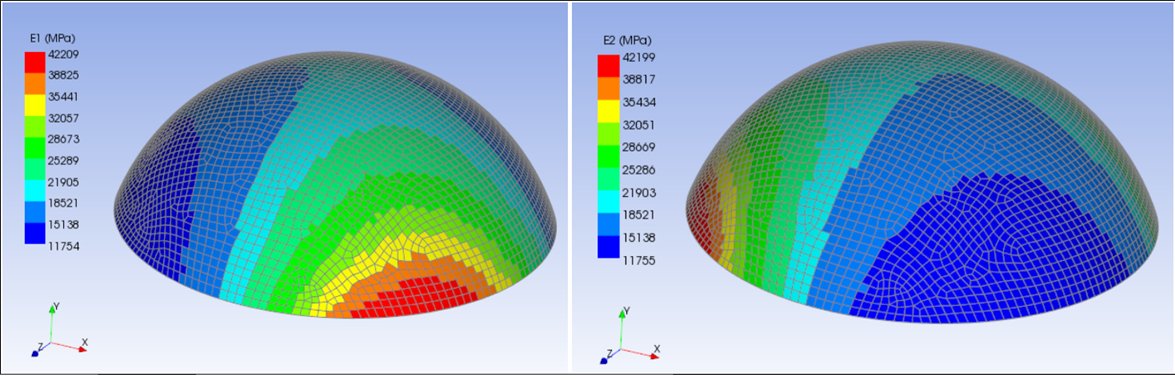
The application automatically considers the result of the draping simulation when evaluating the effective material properties in downstream analyses and postprocessing. In ACP, you can plot the effective material properties (for example, the Young's modulus) as a function of the Shear Angle using Material Plot.
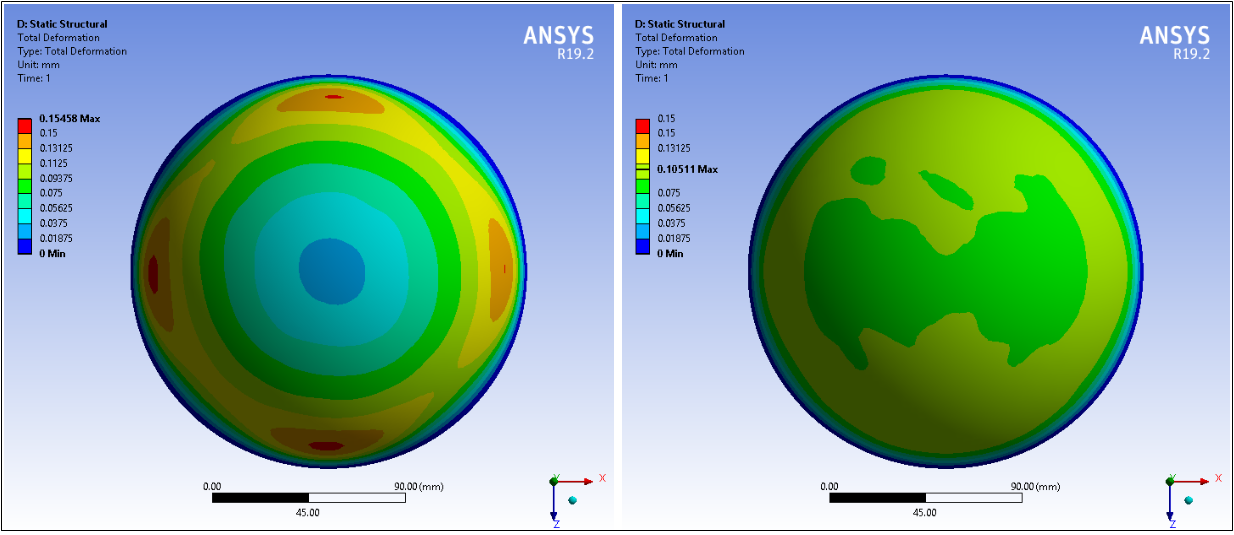
Analysis
The composite model is passed to a structural system to analyze the effect of a uniform pressure load. It is worth comparing the result with the one obtained considering a constant material and no draping: in the latter case the maximum deformation is underestimated by more than 30%.