There are two ways to import an external geometry into ACP:
The first option is directly through ACP, directly importing copies of the CAD file into the user_files directory in the Workbench file structure. Any further changes to the original file are not transferred.
By selecting the Setup cell of your ACP system and then selecting the Load Model Properties option (Geometry category of the Properties of Schematic) in Workbench. The advantage of this option is that the CAD geometry can be refreshed inside DesignModeler or SpaceClaim.
For either case, the geometry remains intact when a project is archived and restored.
Note: For CAD geometries imported from SpaceClaim, the entire geometry from SpaceClaim is imported into ACP. In addition, bodies with the Suppress for Physics option activated are imported.
The parts included in an imported CAD geometry are displayed once the CAD geometry is up-to-date. If the imported CAD geometry is an assembly of parts, multiple parts are shown in the Tree underneath the CAD geometry. ACP makes the distinction between four different types of parts:
Face (
 ): Single
face
): Single
faceSurface (
 ): Single
surface body
): Single
surface bodySolid (
 ): Single
volume body
): Single
volume bodyCompound (
 ):
Combination of multiple connected surfaces and/or
bodies
):
Combination of multiple connected surfaces and/or
bodiesPerformance:
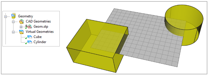
Features based on a CAD geometry can demand a lot of computational resources if you apply them to areas with many elements and/or nodes. You can improve computational performance by splitting the CAD Geometry into smaller parts so you are working with multiple Virtual Geometries as shown below. The reason is that costly computations are only performed for the elements and/or nodes which are inside the bounding box of the selected geometry. Of course, this improves performance only if the intersection between the bounding box of the geometry and shell mesh is small.
In the example below, it is more efficient to work with two Virtual Geometries because the bounding box of each individual shape is much smaller than the shell mesh and so the costly computations are performed only for a few shell elements instead of the entire mesh.
Loading a CAD Geomety can become slow if the CAD file contains many separate shapes due to a system limitation. The workaround is to import multiple smaller CAD files.
Geometry import has the following options:
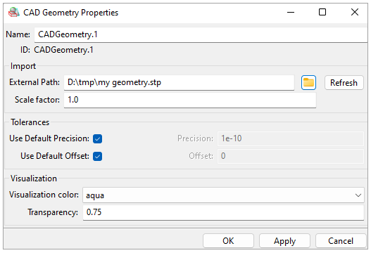
Name: Name of geometry for use in the database.
External Path: Location of the geometry file to be imported.
Refresh: Reload the file from the external path. The file is automatically copied to the Workbench project folders.
Scale Factor: Scale the geometry in the global coordinate system (useful for change of units).
Precision: Precision of the imported geometry. This value is used to evaluate intersections and other geometrical operations.
Offset: Sets the default capture tolerance value associated with the CAD geometry for operations such as the Geometrical Selection Rule.
Use Default Offset: Boolean which sets the offset to 10% of the average element size.
Visualization Color: Color in which the imported geometry is displayed.
Transparency: Transparency of the imported geometry (value between 0 and 1).
Assemblies should be imported as a single .STP file rather than individual ones containing links.
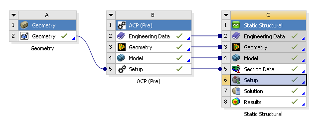
The geometry component in Workbench can be used to link CAD geometries with ACP-Pre. The linked geometry is scaled automatically if its units do not match those of the project. The required steps for geometry import are:
Add a Geometry component to the project.
In the context menu of the Geometry select Import Geometry
Link the Geometry cell to the ACP (Pre) Setup cell
The imported geometry appears under CAD Geometries in ACP.