


Topics in this section:
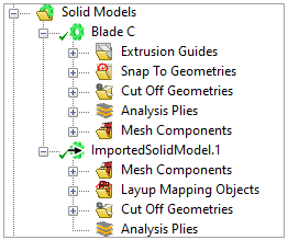
ACP knows two different types of solid models: the first type is simply called Solid Model and is based on an extrusion algorithm that generates a volume mesh from the shell mesh and its Composite Definitions. The second type is named Imported Solid Model and maps the Composite Definitions onto an external (imported) solid mesh.
Because of its geometrical limitations, you can only use the standard Solid Model for simple to moderately complex lay-up models and shapes. You can customize the extrusion of the lay-up using Extrusion Guides, Snap-To Geometries, and Cut-Off Geometries. Still, the extrusion can result in highly distorted layered solid elements if the shell reference surface is highly curved and the laminate is thick.
The Imported Solid Model is a good alternative because the solid mesh is generated independently of the lay-up. The solid mesh is loaded in ACP, and the lay-up (Composite Definitions) from ACP is mapped onto the external solid mesh. With the Imported Solid Model, you can choose to map the lay-up using layered or reinforcing elements. The latter eases the solid mesh constraints since it enables the use of any solid element type (brick, tetra, etc.). Meanwhile, layered elements require a solid mesh with brick or prism elements.
The context menu of the Solid Models object contains these actions:
Create Solid Model: creates a new solid model object
Paste: adds a new solid model object from the clipboard
Note: The Imported Solid Models can only be created via the Workbench Project Schematic. See the Solid Modeling workflow section.