


The following figures show the Model Properties dialog window in both Workbench and Stand Alone mode.
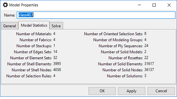
In Stand-Alone mode, the Format, Input File Path, and Input File Unit System properties become editable and are used to import the shell reference surface (shell mesh). The Model Statisticstab gives an overview of model statistics including number of materials, stack-ups, etc. The full list of Model Statistics are shown in Figure 2.4: Model Statistics below.
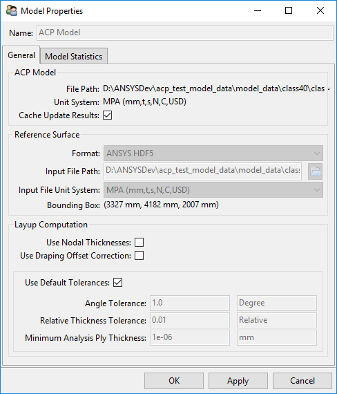
The ACP Model section of the Model Properties dialog displays the path to the ACP model file. The unit system of the ACP model is also displayed. This unit system can be changed in the Units menu. The selected unit system is displayed in the status bar at the bottom of the ACP window.
The property Cache Update Results controls whether the update results (i.e ply extents, analysis plies, solid models) are stored. This allows you to reopen the most recently used lay-up model state and improves the application's performance. You can disable this feature in order to reduce the size of the .ACPH5results file. Note, if the feature is disabled, you will be prompted for a model update whenever the ACP Model is reopened.
The file path to the input file of the reference surface is set in the Reference Surface section of the Model Properties dialog.
In Workbench, the reference surface is automatically transferred to ACP in the Ansys HDF format. In this case, the reference surface unit system is fixed.
In Stand Alone mode, the input file path for the reference surface is set here. The input file can be a .DAT (generated by Workbench), .INP, or .CDB (generated by Mechanical APDL with CDWRITE). The unit system for the reference surface can be set if it is not defined in the input file.
The unit system must be defined in Stand Alone mode when importing or exporting a model in .HDF5 format and also when exchanging material data with the database or ESAComp.
The bounding box describes the dimensions of the reference surface in xyz-space.
The options defined in this section are described below:
Angle and Relative Thickness Tolerance
ACP transfers the Composite Definitions into Section Data so that they can be interpreted by Ansys Mechanical. In the case of curved surfaces or draped laminates, sections may change continuously with every element as their orientations change. This generates information which can reduce the performance of data transfers and solvers. To avoid this, ACP groups section data of multiple elements together within a certain tolerance range.
The Angle Tolerance field sets the allowable ply angle tolerance between the same layers of neighboring elements. The Relative Thickness Tolerance field applies to the individual layer thickness as well as the global lay-up thickness. For two elements to be included in the same section definition, the difference of the angle and the relative thickness of every ply must be within the defined tolerance. Core materials are typically thicker than a laminate by a factor of 10 or more. As such, the thickness tolerance is defined as a relative rather than an absolute value. The default tolerance values are very small compared to the manufacturing tolerances of composites. The loss of accuracy is negligible.
Minimum Analysis Ply Thickness
Cutting operations used in ACP can cut an analysis ply to a thickness thinner than the specified ply thickness. For example, if a Cut-Off geometry intersects a ply at its vertical mid-point, it will slice the ply in half. When the intersection occurs at ply boundaries, an extremely thin layer can appear as the result of geometric tolerances of CAD files. These extremely thin layers are of the order of magnitude of 109 and are purely the results of numerical imprecision. The Minimum Analysis Ply Thickness field sets a thickness threshold below which no such plies can arise.
The global default values for the above mentioned tolerances and thickness are set in the Section Generation dialog but can be overridden in the Model Properties dialog.
Use Nodal Thicknesses
ACP supports ply with variable thickness and Ply Tapering. By default, the thicknesses are evaluated at the element centers, but for Ply Tapering and Cut-Off operations, it can be worthwhile to evaluate them on a per-node basis. This additional data further refines the lay-up representation in ACP and is used in shell and solid model analysis. The option Use Nodal Thicknesses enables the node-based thicknesses evaluation. For more information, see Element- vs. Node-based Thicknesses.
Use Draping Offset Correction
By default, during draping simulation, the application lays the draping mesh on the reference surface of the model independently of the lay-up thickness. However, for thick laminates, such as sandwich structures, with Ply Tapering and Drop-Offs, this approach can lead to inaccurate results. If you enable the Use Draping Offset Correction option, the draping mesh follows the bottom offset (relative to the reference surface orientation) of the selected ply. This allows the application to account for the lay-up thickness and, as a result, provides a more accurate draping simulation. Enabling offset correction for thick and curved laminates also improves the precision of the boundary and area for the flat wrap of the ply.