
Using the Diagram Editor to Create a Model
You can use the Diagram Editor to create models.
- Add a model in one of these ways:
- Click Twin Builder > Add Model.
- Right-click the Models folder under Definitions in the project manager.
- Press Ctrl + Shift + M.
- Click Tools > Edit Libraries > Models. The Edit Libraries dialog box appears. Click Add Model.
The Add Model dialog box appears with the previous model type selected:
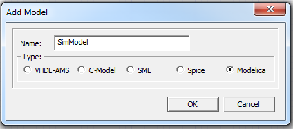
- Enter the name and click OK. The model file opens in the Diagram Editor in a separate tab.
If an editable model has been imported, you must add a new Diagram Editor. Either click the Add Diagram Editor  icon in the toolbar, or select Modelica Model Editor > Add Diagram Editor.
- From the right side of the Diagram Editor, drag a component to the Diagram Editor. Press Esc to complete the action.
- To move a component after placing it, select and drag it.
- To rotate a component before placing it, press R before releasing the mouse click.
- To rotate a component after placing it, select it and press Ctrl+R, which rotates it by 90°, or right-click the component and select Rotate.
- To delete a component, select it and press Delete, or right-click and select Delete.
When you rotate a block or component, the Diagram Editor removes wires connected to unselected components. You must reconnect the blocks and components.
When you delete a block or component, the Diagram Editor removes all connected wires.
For more information, see Component Libraries.
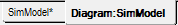
- After arranging the components, use wires and connectors to connect the components. Click the input/output pins of the component and connect them to the desired pins.
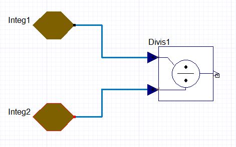
- For Modelica models, if the component has an array interface port and you make a connection, you can select the connection and change the default value of 1 for "ArrayIndexOfConnectionX" in the Properties window.
- After you complete the diagram, edit the properties and parameters of the components in the Properties Manager dialog box.
- Click Modelica Model Editor > Update Text from Diagram or click the Update Text from Diagram icon on the Modelica ribbon. For more information, see Updating Text from Diagram.
Related Topics
Operations in the Diagram Editor
Reverting Diagram Editor Changes
Modelica Diagram Editor Settings