
Using a 3D Layout Component
HFSS 3D Layout designs can be imported into Maxwell as a component for simulation in a Maxwell 3D transient analysis. You can have a complex layout component interact with the surrounding 3D geometries without the burden of using a 3D geometry exported from HFSS 3D Layout. This feature allows great scalability in having a complex layout geometry sit in an EMI/EMC 3D environment.
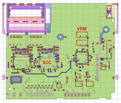
The layout component can be imported from EDB to a Maxwell 3D design with a terminal solution type.
Supported functionalities for Layout Component in Maxwell 3D include
-
Normal simulation workflow: Run simulation and view matrix and field overlay
-
Layout geometry visualization and option to change object visualization attributes.
-
Flex PCB Component support
-
Visualize RLC elements in layout components the same way as they do in 3D layout, including RLC boundaries and components that are categorized as circuit elements.
-
Parametric Analysis: Using design variable to control component
-
Import of custom coordinate systems from layout component design to Maxwell 3D.
-
Intersection Validation
- Between MCAD geometry and layout component
- Between different layout components
-
Show Nets for Layout Components
- Only MCAD nets are shown now, which may connect through ECAD conductors
- Net attributes can be view through component object attributes
-
Port Display
-
Mesh Link
-
FEBI/Hybrid Regions
-
Can use non-model sheet or cut plane to plot in layout component
Limitations:
- Single top design EDB only
- No Derivative support
- No Encryption
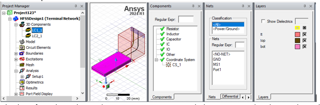
When a layout component is selected in the Project Manager tree or history tree, the Components/Nets/Layers tabs will display the information about the component in the same way as they do in a 3D layout design for that component.
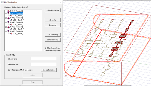
Finally, in the Net Visualization dialog, edge ports are correctly identified as part of the nets formed by ECAD and MCAD geometries.
Related Topics
Inserting a Layout Component Instance
Using Layout Custom CS for Placement
Editing a Layout Component Definition
Visualization for Layout Components in 3D Modeler
Visualization for RLC Boundaries and Component Groups Designated as Circuit Elements
Show Nets for Layout Component
Field Plots on Layout Component's Layer or Net