
Inserting a Layout Component Instance
Once you have added a layout component to a design, you can insert additional instances of it easily, duplicating the definition of the first one. Access the command using one of the following two methods:
- Right-click 3D Components in the Project Manager and choose Insert Instance > {Layout_Component_Name}
- From the menu bar, select Draw > 3D Component Library > Insert Instance > {Layout_Component_Name}
Additional instances of a layout component will be inserted at the same location as the original one. Select each additional instance under 3D Components in the Project Manager and move it to the desired location, eliminating any overlap between the layout components.
If you later decide to change any property in the layout component definition, use the Edit Definition function. However, be aware that changing the definition in this manner affects all instances of the component.
For variations to occur between instances of the same component, at least one project or design variable must be defined and used in the source layout. Instance variation is achieved as described below.
Instance Variation
The prerequisites for using design variation are
- at least one project or design variable must be defined in the HFSS 3D Layout source design.
- the variable must be used to define a model property (such as a layer thickness, trace width, or object location).
To define a layout component with variable mapping:
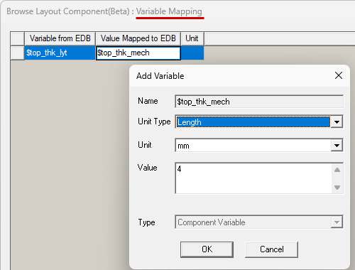
While adding the layout component to your Maxwell design, do the following when you reach the Variables Mapping step of the Browse Layout Component wizard:
- In the Value Mapped to EDB column, replace one or more numerical values with the name of a local variable.
- Press Enter.
- Select the Unit Type and Unit from the drop-down menus.
- Optionally, change the prepopulated Value, which initially equals the value assigned to the associated variable in the source layout.
- Click OK.
- Repeat steps 1–4 for any other variables you wish to map between the target and source designs.
- Click Next.
- Optionally, choose whether or not to Map instance parameters to variables. If you select this option, use the drop-down menu to choose whether to create local Design or Project variables.
- Click Finish to complete the component definition.
If the name you specified has not already been defined, the Add Variable dialog box will appear.
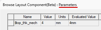
The Parameters step of the Browse Layout Component wizard appears. It lists the design and project variables and the current numerical value of each:
Regardless of whether you choose to map parameters to local variables or not, each parameter will be exposed as a property of the layout component instance, and the value can be manipulated independently for each instance.
To insert two or more instances of the layout component:
- Insert one or more additional instances of the layout component as detailed near the top of this page.
- Move the additional instances of the component so that they don't overlap the first one. Locate as desired.
- Under 3D Components in the Project Manager, select the instance for which you want to change a mapped parameter (such as "LC1_2").
- In the Parameters tab of the docked Properties window, change the Value of one or more parameters and press Enter.
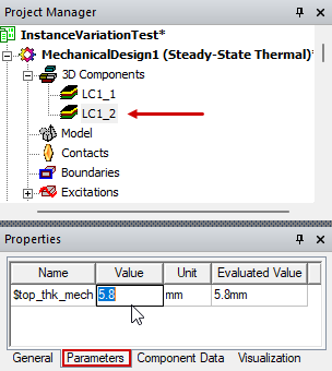
The geometry changes should be immediately visible in the Modeler window. Position the viewpoint and zoom in/out as required to clearly compare the geometry for each instance.