
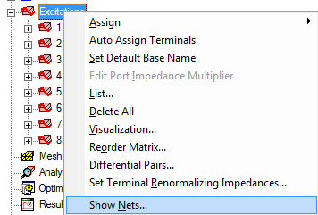
Show Nets for Layout Components
For Terminal Solution types, Maxwell designs that include Layout Components, you can use the Show Nets command to visualize conducting nets and terminal associations formed by 3D geometries and layout components in a Maxwell design. In the Net Visualization dialog:
- All nets can be correctly identified including 3D geometries and layout components with correct terminal associations.
- All the functionalities are supported for nets containing layout component objects.
- Tools included in the Net Visualization dialog help users quickly select specific nets containing layout component objects.
The Show Nets command can be accessed from the Maxwell > Excitations menu and by right-clicking on Excitations in the Project Manager tree.
For Terminal Solution types, you can use the Show Nets command to visualize DC continuity and terminal associations for 3D conductors and terminals assigned to the edge/face of 2D objects when the 2D object or its face is assigned as a "Port" (terminal is always assigned on a port) or the port is touching the 3D conducting object.
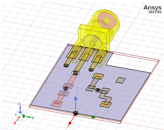
Selecting Show Nets... displays the Net Visualization dialog that lists the nets and associated terminals and includes any included Layout Components. Consider the following example design.
The Net Visualization dialog will open as shown below.
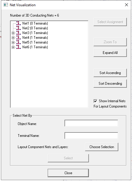
If there are layout components in the design, the Net Visualization dialog displays additional buttons and features to help you quickly select nets containing specific layout component objects. A check box named “Show Internal Nets For Layout Components” is located below the Sort Descending button. If you uncheck the box, the dialog will hide all nets that are formed completely by objects from a single layout component.
In the “Select Net By” section, the “Object Name” search supports layout component objects. By typing a layout component object name in the text box and selecting “Select”, all nets containing objects with that name will be selected. To search for an object name belonging to a specific layout component, you can use the format Component_Name:Object_Name in the text box, such as LC1_1:Via_1. This way, only nets containing this specific object will be selected.
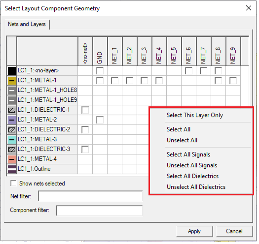
In the same Select Net By: section , a search called “Layout Component Nets and Layers” is added for layout components. Clicking the Choose Selection button to display a Select Layout Component Geometry dialog as shown below.
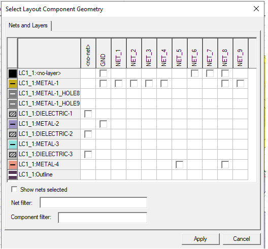
With the Select Layout Component Geometry dialog, you can select objects from layout components’ local nets and layers and search for nets in the overall design that contain these objects. This dialog displays all the layers and local nets of every layout component in the design. If there are objects in the layout component that belong to a specific layer and net, a checkbox will become available for you to select. Once you make selections and click Apply, you can go back to the parent Net Visualization dialog and click Select button, which selects all the nets in the Net Visualization dialog that contain these objects.
The Select Layout Component Geometry dialog is modeless, that means you can work in the 3D modeler while keeping this dialog open. This way, you can use the modeler window to better find the layout component objects you want to search for.
By clicking the column headers, you can select or un-select checkboxes in the entire column. The “Show nets selected” check box can be toggled to move all the selected nets to the left side of the table. Use the Net filter and Component filter to filter fields to designate specific nets and components. These filters support ‘*’ and ‘?’ wildcards and can delimit multiple filters with comma. The table is refreshed each time users update the filter text.
Additionally, the Select Layout Component Geometry dialog has a right-click menu as shown below.
You can use the dialog to select any net or terminal. You can continue to work in the Modeler window with the dialog open.
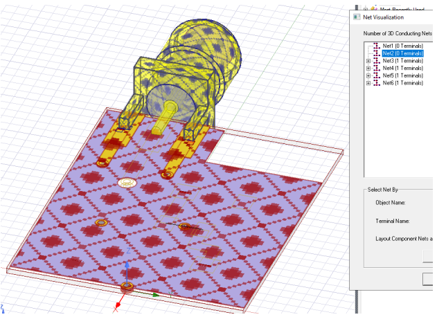
The Net Visualization dialog identifies all nets and will include both 3D geometries and layout components with correct terminal associations. As shown in the figure below, any net you select in the Net Visualization list highlights the objects in the net in the modeler window. By default, 3D geometries are highlighted with blue texture, and objects from layout components will be highlighted with red texture. The rest of objects in the layout component not belonging to the selected net will be shown as wireframes.
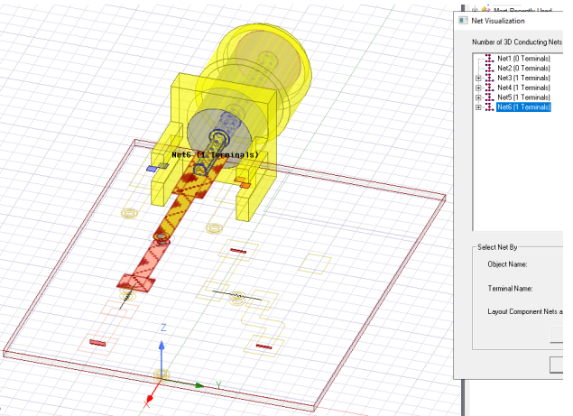
The next figure shows a different selection from the list of 3D conducting Nets to illustrate the changed highlighting.
All the functionalities in the Net Visualization dialog that works for regular nets are also supported for nets containing layout component objects, such as Zoom To. Due to layout components not having any actual geometries in the modeler window, the “Select Assignment” will only select 3D geometries in each net.
Related Topics
Using Layout Custom CS for Placement
Visualization for Layout Components in 3D Modeler
Visualization for RLC Boundaries and Component Groups Designated as Circuit Elements
Show Nets for Layout Component
Field Plots on Layout Component's Layer or Net