
Adding a 3D Layout Component
Use the following procedure to add a layout component to a Maxwell design. These instructions assume that an HFSS 3D Layout of the PCB to be analyzed already exists:
- In the Project Manager, right-click 3D Components and choose Browse Layout Component from the shortcut menu.
- Optionally, change the Name from its default value (LCx, where x is an automatically incremented serial number).
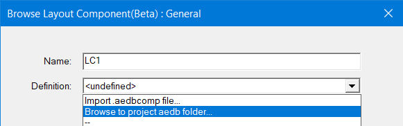
- From the Definition drop-down menu, select one of the following options:
-
Import .aedbcomp file:*.aedcomp files are layout components exported from an HFSS 3D Layout design. When you select this option, the Select layout component file to import dialog box appears. Navigate to the desired file's location, select the file, and click Open.
-
Browse to project aedb folder: HFSS 3D Layout design files are stored in a folder named <Project_Name>.aedb. If the source project contains more than one design, the design name will also be included (<Project_Name><Design_Name.aedb). When you select this option, the Select aedb folder to import dialog box appears. Navigate to the desired folder, double-click it to display its top-level contents, and click Open to select the folder.
-
<Project_Name><Design_Name>: If another design, aside from the current Maxwell one, exists in the same project, and it contains a compatible layout component, the list will include an entry in this form. Select it to include the same layout component in the active Maxwell design.
-
<Project_Name>: If a layout component has previously been added to the active Maxwell design, the project name will be listed in the drop-down menu, even if the component has since been deleted. You can select the project name from this drop-down menu to re-add the component to the design. If you were to select it while the component already exists in the design, a duplicate layout component, overlapping the original one, would be added. Therefore, avoid doing this.
- Click Next.
- What appears at this point depends on whether variables are defined in the source layout and are applicable to the current solution type. Choose one of the following two actions:
- If there are no applicable variables in the source layout, skip to step 4.
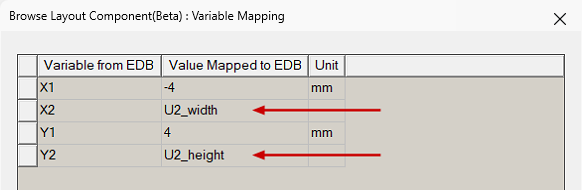
- When applicable variables are present in the source layout, the Variable Mapping step of the Browse Layout Components wizard appears, and the following actions are possible:
- Optionally, you can substitute local variable names for the numeric values in the Values Mapped to EDB column. This is particularly useful if you wish to include multiple instances of the layout component in a single design and have geometry variations between the instances. See Instance Variation for more information.
- Click Next.
- In the Coordinate System window, select a Global Coordinate System as reference or one of the coordinate systems from the layout.
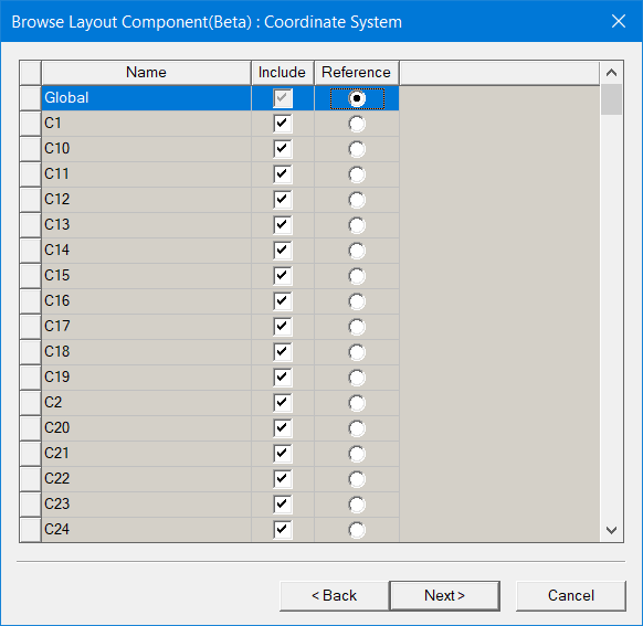
Layout component import supports relative CS placement, move, rotate, etc. Once imported, the layout ports will be created in the Project Manager tree. The bounding box and ports have actual Maxwell 3D geometry while others are not selectable and are only for visualization.
-
Click Next. The Parameters step of the Browse Layout Component wizard appears.
- If you chose not to define local variables in the Variable Mapping step, or if the source design contains no variables, none will be listed in the Parameters step. Skip to step 7.
- Optionally, toggle the selection of Map instance parameters to variables as preferred.
-
If the Map instance parameters to variables option is selected, choose either Design or Project from the adjacent drop-down menu to specify the type of local variable to create.
As previously stated, the variable name will be prefixed with a dollar sign ($) automatically when you choose to create local Project variables.
- Click Finish.
-
Optionally, you can change the visualization characteristics of the layout component; see Visualization for Layout Components for more details.
-
In object selection mode, select all layers of the layout component and assign a length-based mesh operation on the selection. Set the maximum element length to be three to four times the width or height of the grid cells, whichever is the lesser.
The General step of the Browse Layout Component wizard appears:
If you do specify a previously undefined local variable name, the Add Variable dialog box will appear when you press Enter so that you can define its unit type, units, and initial value in-place.
In the following example, two of the four variables in the source ECAD database (X2 and Y2) have had local variables substituted for the original numeric values:
If the original layout design includes additional CS, these are included as properties to the layout component in Maxwell 3D. As you select the original layout design to import to Maxwell, you can choose a custom coordinate system as the reference CS. After creation in Maxwell, you can choose a target CS for the layout component, and the component will be moved to a place where its reference CS snaps to the target CS. This can simplify placement in Maxwell.
Otherwise, when you have defined local variables in the Variable Mapping step, they will be listed in the Parameters step along with their values and units.
The following figure shows the parameters with two local variables substituted for numeric values (as shown in the preceding figure):
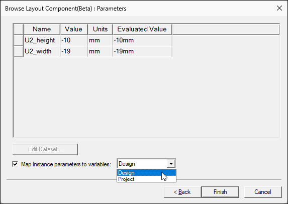
You can choose whether to keep these mapped variables only as instance parameters or to also create local Design variables or Project variables, as follows:
Alternatively, if you also wish to include the mapped variables as Maxwell design or AEDT project variables, select this option and choose between the two types in the next step.
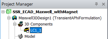
The layout component name appears under 3D Components in the Project Manager. An instance number ("_1" in this case) has been appended to the component name:
Typically, you need not enforce the maximum element length inside the selection. For the majority of printed circuit boards, there will only be one element through the thickness of any layer due to their thinness. For more information on meshing layout components, see Meshing Recommendations for a Layout Component.
Related Topics
Visualization for Layout Components
Editing the Definition of a Layout Component