
Assigning Frequency Dependent Material: Nonlinear Drude Input
When you select Nonlinear Drude Input as the model for the frequency dependent material property, the Nonlinear Drude Input window appears. Drude materials are now supported by the Transient solvers, producing plasma density data within the material domains. This means that plasma density plots can be produced.
From this window, you can enter material property values and view a plasma frequency vs. electric fields plot.
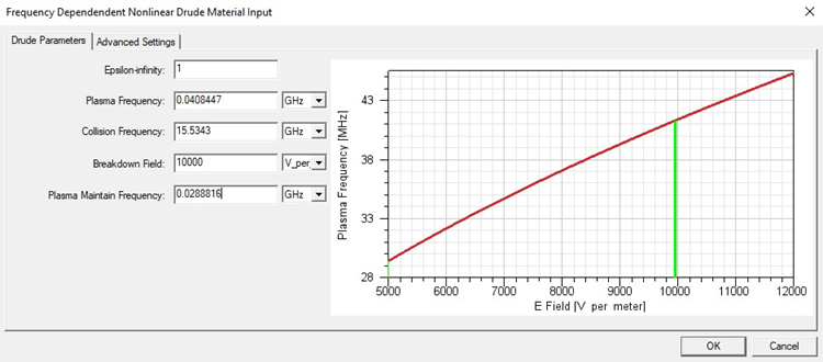
The main parameters of a nonlinear Drude material are the epsilon-infinity ε∞, the plasma frequency fp, the collision frequency fc, the breakdown field Eb, and the plasma maintain frequency fm. Given first three parameters, the relative permittivity is defined as
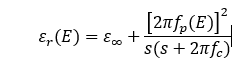
where s=j2πf is the complex frequency, ε∞ and fc are constants, and fp is a function of the time-dependent field strength E=|E(t)|.
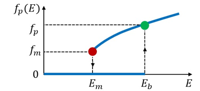
When the electric field strength E increases from zero then exceeds Eb, the discharge is on. The plasma frequency is uniquely determined by a parabola symmetric to the x-axis and passing through points (Em,fm ) and (Eb,fp). Once the discharge is on, the lowest field strength for maintaining the discharge is Em=Eb⁄2 and the corresponding plasma maintain frequency is fm. When E drops below Em, the discharge is off and fp(E) becomes zero. No matter if the discharge is on or off, εr has a nonzero contribution from ε∞, which is usually set to one due to the background gas being in low pressure.
Because the plasma is generated by microwaves, the radiation must be able to penetrate the plasma in order to ionize atoms and molecules. This happens when

You must be cautious about selecting the frequency f of the harmonic input signal while setting up a transient excitation.
Advanced Settings
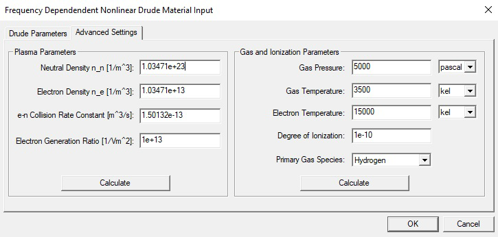
The Advanced Settings tab includes settings for Plasma Parameters and Gas and Ionization Parameters.
Advanced Settings: Plasma Parameters
The plasma and collision frequencies can be derived from more fundamental parameters obtainable through plasma diagnostics. Given the electron density ne, the plasma frequency fp is equal to 1/2π √((ne e2)/(me ε0 )), where e and me are the charge and mass of an electron, respectively. Given the neutral density nn and the electron-neutral collision rate constant ven, the collision frequency fc is equal to vennn.
Once the setup of nn, ne, and νen is done, press Calculate. The plasma and collision frequencies on the Drude Parameters tab will be updated accordingly.
The electron generation ratio γ is mainly used for plasma density plot and will be explained later.
Advanced Settings: Gas and Ionization Parameters
Considering the plasma parameters are not always available without a plasma being generated and measured, there is another option to estimate plasma and collision frequencies from gas parameters. Given the pressure p and the temperature T of the discharge gas, the density of the neutral atoms can be derived from the ideal gas law
nn=p/(kBT) ,
where kB is the Boltzmann constant.
Given the degree of ionization to be α and assuming the plasma is quasi-neutral, the electron density can be calculated by
ne=α/(1-α) nn ,
where 0<α<1.
The electron-neutral collision rate depends on the primary gas species and the electron temperature.
After you edit the above parameters and click Calculate, the Drude Parameters tab updates accordingly.
Plasma Density Plot
The procedure for creating a plasma density plot resembles that for a transient field plot.
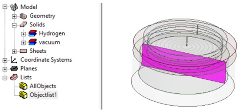
First, create face or object lists for observing plasma densities and transient fields.
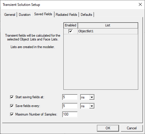
Next, use the Saved Fields tab of the Transient Solution Setup to select the face or object lists. By checking the boxes you can enable the Start saving fields time, and Save fields at interval. When you select a face or an object list, you can also specify the Maximum Number of Samples.
The time-varying electron density is calculated by:
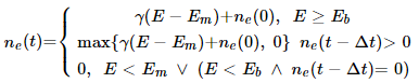
The initial electron density ne(0) is the electron density meε0(2π fm/e)2 specified by Plasma Parameters. The electron generation ratio γ characterizes the efficiency of electron generation with respect to the field variation E(t)-Em. Without clicking Calculate in Plasma Parameters, you can set ne and γ independently from other parameters to calibrate the plasma density plot.
Outside Drude materials, the plasma density will be zero. Besides, for a ramped sinusoidal excitation, the initial electric field is zero for the entire simulation domain. Therefore, the plasma density is also zero at the beginning of a transient simulation.
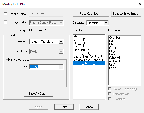
When you create a Field Plot on a transient project with a Nonlinear Drude Material involved, the Quantity menu allows you to select Plasma_Density_t.
You can animate such a Plasma_Density_t plot. The following animation shows the plasma density in an inductively coupled plasma (ICP)-CVD chamber excited by a 13.6 MHz sinusoidal signal.