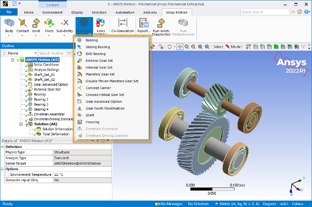
The Drivetrain Toolkit helps you to add power transmission devices including gears, bearings, shafts, and housings to your Mechanical system. Motion then enables you to analyze the gear excitation force under fluctuating speed and load conditions.
The toolkit enables you to configure the gear pair model by entering the specifications required for the gear design, and by analyzing the transmission errors (such as backlash) for each gear. To improve your modeling experience, the toolkit provides catalogs from major bearing manufacturers, and enables gear geometry to be created automatically.
A shaft is the base object of a drivetrain model, to which you can connect other components such as bearings and gears. You can also attach a housing and then use the drivetrain assembler to create bearing raceways at the desired positions. Finally, you can use a drivetrain driving scenario to introduce an input driving condition.
Once the drivetrain system is complete, Motion enables you to analyze its dynamic characteristics.
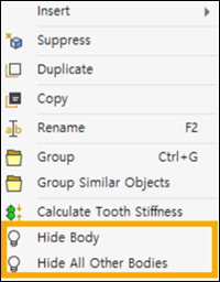
The bodies created by Drivetrain Toolkit objects can be hidden or displayed by right-clicking the object in the tree and selecting or (see Figure 2.8: Body Display Options).
In a mechanical system, bearings separate moving parts and take a load. Bearings constrain relative motion and reduce friction.
Bearings can be created by entering their dimensional properties or by selecting a model from a manufacturer catalog.
Motion provides a fast and stable stiffness model between two raceways. During the analysis, stiffness depends on the loading condition throughout the analysis.
There are basic bearing designs available using libraries from each company (NSK, SKF, KOYO, FAG).
Bearing geometry is created automatically using the option available from the context menu for Shaft, Concept Carrier, Housing, or Drivetrain Assembler objects.
Basic rating life can be calculated based on ISO/TS 16281 using the option.
Bearing objects have the following details:
- Bearing Type
The type of standard bearing to create. Choose , , , . Based on your choice, you may need to define further details.
- Filter
These details are available for all bearing types.
- S, N, K, F
Determined by the manufacturer of the bearing.
- Bore
If set to , you must also define a Min and Max bore size.
- Outer Diameter
If set to , you must also define the Min and Max outer diameter of the bearing.
- Width
If set to , you must also define the Min and Max bearing width.
- Bearing Catalog
Choose a model number from the catalog to import bearing details based on the specifications of standard bearings.
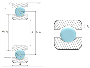
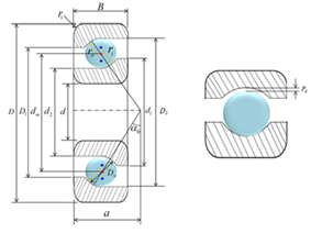
- Radial Ball
These details are only available if you choose as the Bearing Type.
- Bore
The diameter of the open center (d) of the bearing.
- Outer Diameter
The outer diameter (D) of the bearing.
- Width
The width (B) of the bearing.
- Ball Pitch Diameter
The center-to-center diameter (dm) of the rolling elements.
- Number of Balls
The number of balls contained in the bearing.
- Ball Diameter
The diameter of the balls contained in the bearing.
- Inner Raceway Shoulder Diameter
The shoulder diameter (d1) of the bearing's inner raceway.
- Outer Raceway Shoulder Bore
The shoulder diameter (D1) of the bearing's outer raceway.
- Rounding Radius
The radius of the rounding on the outer edge (r1) of the bearing's raceway.
- Outer Raceway Groove Radius
The radius of the groove (ro) of the bearing's outer raceway.
- Inner Raceway Groove Radius
The radius of the groove (ri) of the bearing's inner raceway.
- Radial Internal Clearance Type
The gap between the rolling elements and the raceways of the bearing.
- Radial Internal Clearance Value
The play between the ball and the raceway perpendicular to the bearing axis.
- Angular Contact Ball
These details are only available if you choose as the Bearing Type.
Has all of the settings of Radial Ball, but adds:
- Action Point
This value is used to determine the contact angle (a) used to set the action point.
- Contact Angle
This value (ao) is calculated using the Action Point.
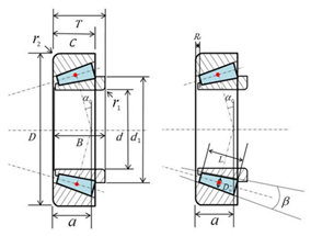
- Tapered Roller
These details are only available if you choose as the Bearing Type.
Has some of the settings of Radial Ball, but adds:
- Width of Cone
The width of a tapered roller cone (B)
- Width of Cup
The width of the bearing cup (C)
- Roller Pitch Diameter
The center-to-center diameter (dm) of the rolling elements.
- Number of Rollers
The number of rollers contained in the bearing.
- Roller Diameter
The diameter of the rollers contained in the bearing.
- Roller Center Point
The center point of the rollers contained in the bearing.
- Roller Length
The length (L) of the rollers contained in the bearing.
- Roller Tapered Angle
The taper angle (β) of the rollers contained in the bearing.
- Cone Shoulder Diameter
The shoulder diameter (d1) of the cone contained in the bearing.
- Rounding Radius of Cone
The rounding radius (r1) of the cone.
- Rounding Radius of Cup
The rounding radius (r2) of the cup.
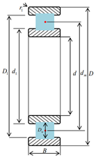
- Cylindrical Roller
This bearing type has some of the settings of Radial Ball and some of the settings of Tapered Roller.
- Strength
- Operating Speed
The operating speed of the bearing. This will be used to calculate bearing life.
- Axial Force
The operating axial force of the bearing. This will be used to calculate bearing life.
- Radial Force
The operating radial force of the bearing. This will be used to calculate bearing life.
- Temperature
The operating temperature of the bearing. This will be used to calculate bearing life.
- Calculation Method
If you have C0r and Cr information to calculate the strength of bearing, choose , otherwise choose to calculate basic load ratings according to ISO standards.
- C0r
The basic static radial load rating of the bearing. For definition, calculation method, and value of C0r, see ISO 76.
- Cr
The basic dynamic radial load rating of the bearing. The constant stationary radial load which a rolling bearing can theoretically endure for a basic rating life of one million revolutions.
- A1
Life adjustment factor for reliability. For a group of apparently identical rolling bearings, operating under the same conditions, the percentage of the group that is expected to attain or exceed a specified life. The reliability of an individual rolling bearing is the probability that the bearing will attain or exceed a specified life.
- Lubricant Type
Choose from , or .
- Cleanliness
Choose the type of cleanliness of the bearing.
- Pr
The dynamic equivalent radial load value, calculated from the bearing input parameters. This is constant stationary radial load under the influence of which a rolling bearing would have the same life as it would attain under the actual load conditions.
- L10 [Rev]
The basic rating life in revolutions (ISO 281). This is rating life associated with 90% reliability for bearings manufactured with commonly used high quality material, of good manufacturing quality, and operating under conventional operating conditions.
- L10 [hr]
The basic rating life in hours (ISO 281). This is rating life associated with 90% reliability for bearings manufactured with commonly used high quality material, of good manufacturing quality, and operating under conventional operating conditions.
- Lnm [Rev]
The modified rating life in revolutions (ISO 281). This is rating life modified for 90% or other reliability, bearing fatigue load, and/or special bearing properties, and/or contaminated lubricant, and/or other non-conventional operating conditions.
- Lnm [hr]
The modified rating life in hours (ISO 281). This is rating life modified for 90% or other reliability, bearing fatigue load, and/or special bearing properties, and/or contaminated lubricant, and/or other non-conventional operating conditions.
- Material
- Assignment
Choose the material that will be assigned to body objects after the geometries are imported.
Sliding bearings can be defined using geometry and contact parameters.
Sliding Bearing objects have the following details:
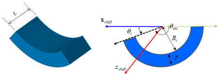
- Geometric Shapes
- Arc Angle
The arc angle of the sliding bearing ( θ arc ). The arc angle determines the arc length of the sliding bearing.
- Length
The length of the sliding bearing (L).
- Thickness
The thickness of the sliding bearing (T).
- Inner Diameter
The diameter of the sliding bearing. It is twice the size of Ri.
- Contact Parameter
- Stiffness
Used to set the stiffness coefficient. Choose from: , , or (Displacement-Force Spline).
- Damping Type
Used to set the stiffness coefficient. Choose from: , , or (Velocity-Force Spline).
- Friction Type
Used to set the stiffness coefficient. Choose from: , , or .
- Number of Axial Contact Patch Size
Used to set the number of axial patches.
- Number of Circular Contact Patch Size
Used to set the number of circular patches.
- Material
- Assignment
Choose the material that will be assigned to body objects after the geometries are imported.
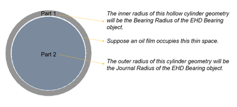
EHD bearings can be defined on a selected General joint. These bearings enable you to generate forces between two bodies separated by a lubrification oil film.
The following are configurable details of EHD Bearing objects:
- Joint
The General joint defined between inner and outer bodies.
- Bearing Radius
The inner radius of the outer part of the bearing object.
- Journal Radius
The outer radius of the inner part of the bearing object.
- Width
The width of the bearing.
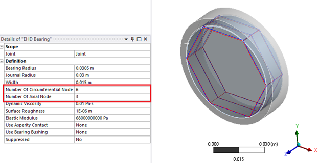
- Number Of Circumferential Nodes
The number of nodes around the circumference of the bearing, which affects the quality of the mesh used in the solver.
- Number Of Axial Nodes
The number of nodes along the axis of the bearing, which affects the quality of the mesh used in the solver.
- Dynamic Viscosity
The dynamic viscosity of the fluid film in the bearing.
- Surface Roughness
The surface roughness of the bearing.
- Elastic Modulus
The effective Young's modulus of elasticity of the contact pair of the bearing.
For more information on EHD Bearing parameters, refer to the Motion Preprocessor Manual.
Gear Set objects allow you to define different type of gear assemblies. Each enables you to define the gear geometry parameters. Create gear geometry automatically from parameters by choosing from the context menu of a Shaft or Concept Carrier object.
External Gear Set enables you to define driving and driven gears for an external gear set.
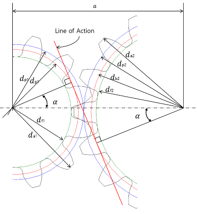
| Parameter | Symbol |
|---|---|
| 1. Module(normal) | mn |
| 2. Helix angle | β |
| 3. Pressure angle(normal) | an |
| 4. Number of teeth | z |
| 5. Profile shift coefficient | xn |
| 6. Center distance | a |
| 7. Pitch diameter | dp |
| 8. Base diameter | db |
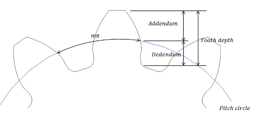
| 9. Addendum | ha |
| 10. Dedendum | hf |
| 11. Tooth depth | h |
| 12. Tip diameter | da |
| 13. Root diameter | df |
External Gear Set objects have the following configurable details:
- Definition
- Gear Profile Generation
Import a gear profile designed in KISSSoft, with all its specifications. For more information, see KISSSoft Interface.
- Type of Gear
Choose from or types.
- Hand of Helix (Helical only)
The direction in which the teeth of the gear are inclined when the gear is laid flat on a horizontal surface.
- Helix Angle (Helical only)
The helix angle (β) of the helical gear contained in the gear sets.
- Module (Normal)
The unit (mn) that determines the size of the gear (
 , where dp is the
pitch circle diameter and z is the number of teeth).
, where dp is the
pitch circle diameter and z is the number of teeth). - Module (Transverse) (Helical only)
Gear modules measured in the plane of rotation. This is calculated automatically (
 ).
).- Pressure Angle (Normal)
The angle at which pressure is transmitted to the teeth of the gear (αn).
- Pressure Angle (Transverse) (Helical only)

- Idler Gear
To add an idler gear, choose from the drop-down menu. Otherwise choose .
- Reference Point
To automatically calculate the reference point (A, B, Z) for modifying the micro-geometry of the gear, choose from the drop-down menu. Otherwise choose to enter the reference point by user input.
- Use Advanced Option
Set to to enable the Advanced Option setting and choose Advanced Gear Options.
- Advanced Option
If Use Advanced Option is set to , choose a Gear Advanced Option object to define the advanced parameters if this gear.
- Initial Angle
The angle that determines the initial orientation of the gear set.
- Center Distance
- Driving to Driven (Ideal)
For a pair of gears, the distance between the centers of the two gears. This is calculated automatically.
- Driving
- Name
The name of the driving gear.
- Quality
Use to set the number of involute point. This value is related to the resolution of the trochoid curve. (The ANSI/AGMA 2000-A88 standard defined 13 quality classes, ranging from 3 to 15. Generally, Motion uses the quality table after below. The default value is "6".)
Application Quality Index Cement mixer drum driver 3 - 5 Cement kiln 5 - 6 Steel mill drivers 5 - 6 Corn picker 5 - 7 Punch press 5 - 7 Mining conveyer 5 - 7 Clothes washing machine 8 - 10 Printing press 9 - 11 Marine propulsion drive 10 - 12 Aircraft engine drive 10 - 13 Gyroscope 12 - 14 - Number of Teeth
The number of gear teeth (z) on this gear.
- Face Width
The width of the face of the gear based on the direction of the axis of rotation.
- Addendum Coefficient
The distance between the pitch circle and tip circle is the addendum, and its ratio to the module is the addendum coefficient.
- Dedendum Coefficient
The distance between the pitch circle and root circle is the dedendum, and its ratio to the module is the dedendum coefficient.
- Profile Shift Coefficient
The value obtained by dividing the amount of profile shift by the module (m). Use a profile shift or addendum modification to modify tooth shape and tooth thickness.
- Tool Tip Radius
Use to set the tool tip radius. This value is related to the radius of the trochoid curve.
- Use Modification
To apply a gear tooth modification to this gear, choose the named modification from the drop-down menu. For more information, see Modifying Gear Teeth.
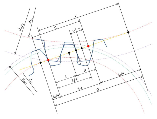
- A Point, B Point, Z Point
These points on the gear are related to the distances and equations shown below.
- Web
To calculate the parameters for gear web geometry automatically, choose from the drop-down menu. Otherwise, choose to enter the following input parameters manually.
- Web Diameter (In)
Defines the inner diameter of the gear web.
- Web Diameter (Out)
Defines the outer diameter of the gear web.
- Web Thickness
Defines the thickness of the gear web.
- Web Mass Information
To calculate the parameters for gear web mass automatically, choose from the drop-down menu, in which case the parameters listed below are calculated using the web geometry and density of the gear. Otherwise, choose to enter the following input parameters manually.
- Mass
Defines the gear web mass.
- Ixx
Defines the moment of inertia about the x-axis for the gear web.
- Iyy
Defines the moment of inertia about the y-axis for the gear web.
- Izz
Defines the moment of inertia about the z-axis for the gear web.
- Tooth Stiffness
To calculate the tooth stiffness of the gear automatically by using the finite element (FE) method, choose from the drop-down menu. Otherwise choose to enter the tooth stiffness spline manually.
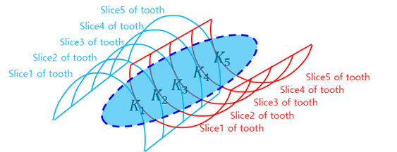
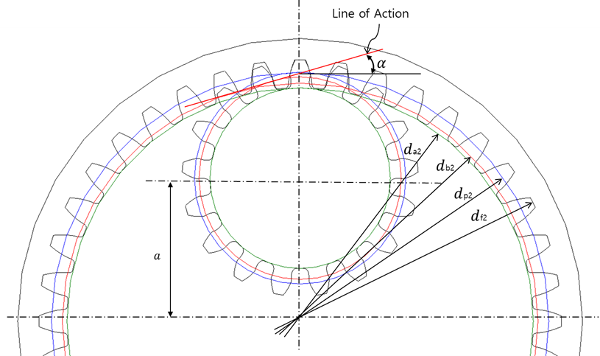
The gear geometry is divided into slices in the depth direction as shown in the figure. Each slice profile can be represented by an involute curve. Gear pairs are contacted on the line of action for each slice. Contact stiffness (that is, mesh stiffness) is calculated from the tooth stiffness pair of the contact points between the driving and driven gear.
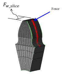
Tooth stiffness is used to represent of the gear flexibility due to tooth bending, root rotation, and Herztian deflection. It can be calculated using the FE method. The gear root is fixed and the force is applied on the surface node. Then the deformation of the node is measured.
- Tooth Stiffness Result
To calculate the gear stiffness, select from the object's context menu in the outline.
Note: Even if the same gear specifications are used, the stiffness results calculated in Motion in Workbench and Standalone Motion may differ slightly. Gear stiffness is a static analysis result and uses just one slice from the gear mesh model. The number of this thin slice used, Young's modulus, and Poisson's Ratio all affect the result, and different default values are used for these properties in Motion in Workbench and Standalone Motion. Using the same settings in both applications should give the same values for stiffness.
- Driven
Driven gears have all the same settings as Driving gears.
- Material
- Assignment
Choose a material that will be assigned to the body objects after the geometries are imported.


Internal Gear Set enables you to define pinion and ring gears for an internal gear set.
| Parameter | Symbol |
|---|---|
| Module (normal) | mn |
| Helix angle | β |
| Pressure angle (normal) | αn |
|
Number of teeth (Ring gear has negative value) | z |
| Profile shift coefficient | xn |
| Center distance | α |
| Pitch diameter | dp |
| Base diameter | db |
| Addendum | ha |
| Dedendum | hf |
| Tooth depth | h |
| Tip diameter | dα |
| Root diameter | df |
Internal Gear Set objects have the following configurable details:
- Definition
Internal gear sets have all the same Definition settings as External Gear Sets.
- Center Distance
- Pinion to Ring Gear (Ideal)
For a pair of gears, the distance between the centers of the two gears. This is calculated automatically.
- Pinion
Internal gear set Pinions have all the same settings as External gear set Driving gears.
- Ring Gear
Internal gear set Ring gears have all the same settings as External gear set Driving gears.
- Material
- Assignment
Choose a material that will be assigned to the body objects after the geometries are imported.
Planetary Gear Set enables you to define sun, pinion, and ring gears for a planetary gear set.
Planetary Gear Set objects have the following configurable details:
- Definition
Internal gear sets have many of the same Definition settings as External Gear Sets, but add:
- Number of Pinion
The number of pinion gears in the planetary gear set.
- Center Distance
- Sun Gear to Pinion (Ideal)
For a pair of gears, the distance between the centers of the two gears. This is calculated automatically.
- Sun Gear
Planetary gear set Sun gears have all the same settings as External gear set Driving gears.
- Pinion
Planetary gear set Pinion gears have all the same settings as External gear set Driving gears.
- Ring Gear
Planetary gear set Ring gears have all the same settings as External gear set Driving gears.
- Material
- Assignment
Choose a material that will be assigned to the body objects after the geometries are imported.
Double Pinion Planetary Gear Set enables you to define sun, pinion, and ring gears for a double pinion planetary gear set.
Double Pinion Planetary Gear Set objects have the following configurable details:
- Definition
Double Pinion Planetary gear sets have many of the same Definition settings as Planetary Gear Sets, but add:
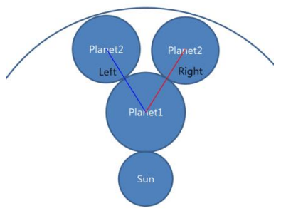
- Dog Leg Direction
Choose between and to determine the location of the second planetary gear with relation to the first planetary gear. The second planetary gear will be placed in one of the two directions shown in the figure.
Assume that the axis of rotation is facing you.
- Center Distance
- Sun Gear to Pinion In (Ideal)
For a pair of gears, the distance between the centers of the two gears. This is calculated automatically.
- Pinion In to Pinion Out (Ideal)
For a pair of gears, the distance between the centers of the two gears. This is calculated automatically.
- Pinion Out In to Ring Gear (Ideal)
For a pair of gears, the distance between the centers of the two gears. This is calculated automatically.
- Sun Gear
Double Pinion Planetary gear set Sun gears have all the same settings as External gear set Driving gears.
- Pinion In
Double Pinion Planetary gear set inner Pinion gears have all the same settings as External gear set Driving gears.
- Pinion Out
Double Pinion Planetary gear set outer Pinion gears have all the same settings as External gear set Driving gears.
- Ring Gear
Double Pinion Planetary gear set Ring gears have all the same settings as External gear set Driving gears.
- Material
- Assignment
Choose a material that will be assigned to the body objects after the geometries are imported.
Crossed Helical Gear Set enables you to define driving and driven gears for an external helical gear set with a cross axis angle.
Crossed Helical gear set objects have the following configurable details:
- Definition
Crossed Helical gear sets have many of the same Definition settings as Helical External gear sets, but add:
- Helix Angle of Driving Gear
- Cross Axis Angle
Use to set the cross axis angle of the pair. This parameter sets a meshing condition.
- Helix Angle of Driven Gear
The helix angle of the driven gear. This is calculated automatically.
- Module
Crossed helical gear set all the same settings as External gear set Driving gears. This is calculated automatically.
- Module (Transverse for driving)
Crossed helical gear set all the same settings as External gear set Driving gears.
This is calculated automatically.
- Module (Transverse for driven)
Crossed helical gear set all the same settings as External gear set Driving gears. This is calculated automatically.
- Pressure Angle
Crossed helical gear set all the same settings as External gear set Driving gears. This is calculated automatically.
- Pressure Angle (Transverse for driving)
Crossed helical gear set all the same settings as External gear set Driving gears. This is calculated automatically.
- Pressure Angle (Transverse for driven)
Crossed helical gear set all the same settings as External gear set Driving gears. This is calculated automatically.
- Center Distance
- Driving to Driven (Ideal)
For a pair of gears, the distance between the centers of the two gears. This is calculated automatically.
- Driving
Crossed Helical gear set Driving gears have all the same settings as External gear set Driving gears.
- Driven
Crossed Helical gear set Driven gears have all the same settings as External gear set Driving gears.
- Material
- Assignment
Choose a material that will be assigned to the body objects after the geometries are imported.
External, Internal, Planetary and Cross Helical gear sets have a Gear Profile Generation property that enables you to import a gear profile designed in KISSSoft (see KISSSoft) with all its specifications.
| Feature | KISSsoft file | Spur | Helical |
|---|---|---|---|
| External Gear | Z12, Z15 | O | O |
| Internal Gear | Z12, Z15 | O | O |
| Planetary Gear | Z14 | O | O |
| Cross Helical Gear | Z17 | - | O |
The interface supports KISSsoft versions 2019 SP3 and later.
For more information about the KISSSoft Interface, refer to the Motion Preprocessor Manual.
The Concept Carrier object is used to assemble planetary gear sets. Select from the context menu create the gear sets components.
Concept Carrier objects have the following configurable details:
- Definition
- Status
Once the inputs are fully defined and geometry creation is performed, the Status will be changed to . after that if the input changes, it will be back to .
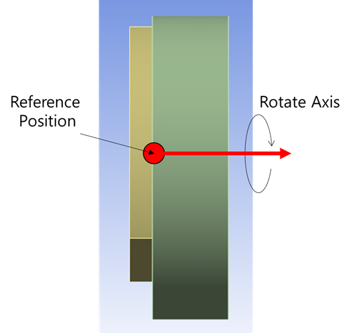
- Coordinate System
Use the coordinate system to set the start position and rotational axis.
- Rotate Axis
Select the rotational direction of planetary gear.
- Pinion Shaft Length
Set the length of pinion shaft of planetary gear.
- Pinion haft Diameter
Set the diameter of pinion shaft of planetary gear.
- Planetary Gear Set
Select the planetary gear set or double planetary gear set to make concept carrier.
- Center Distance
To automatically calculate the distance between sun gear to pinion of the planetary gear, select , otherwise select to enter the input parameters manually.
- Use Carrier Body
To add a carrier body, select , otherwise select .
- Carrier Thickness
Set the thickness of carrier body.
- Material
- Assignment
Choose a material that will be assigned to the body objects after the geometries are imported.
The Gear Tooth Modification object allows you to define advanced gear tooth parameters. The Gear Tooth Modification object can be selected using the Use Modification property of Gear Set objects.
Gear tooth modification objects have the following configurable details:
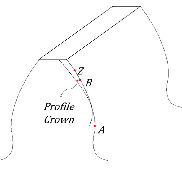
- Profile Crown of Left Flank, Profile Crown of Right Flank
The profile crown is shown in the figure below:
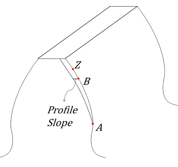
- Profile Slope of Left Flank, Profile Slope of Right Flank
The profile slope is shown in the figure below:
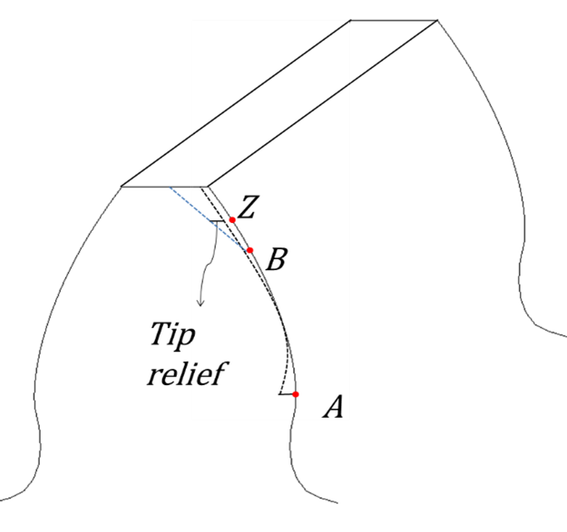
- Tip Relief of Left Flank, Tip Relief of Right Flank
The tip relief is shown in the figure below:
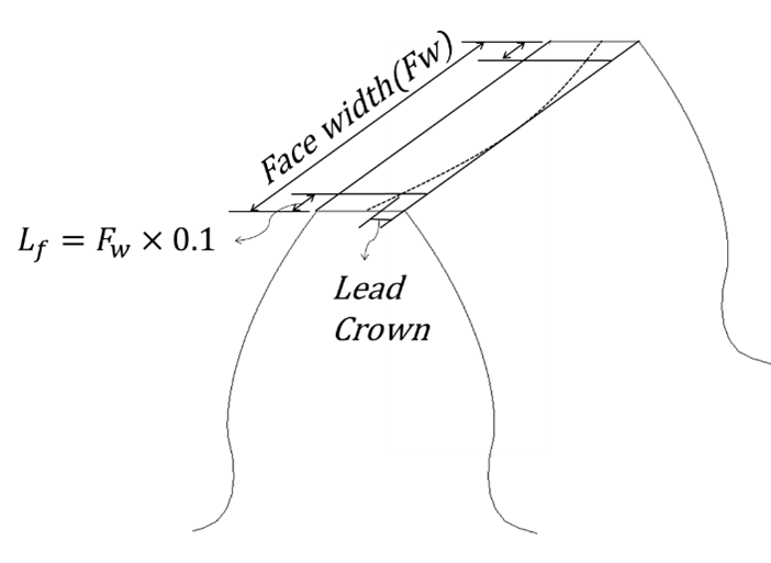
- Lead Crown of Left Flank, Lead Crown of Right Flank
The lead crown is shown in the figure below:
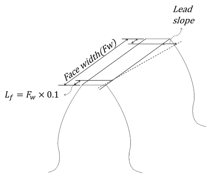
- Lead Slope of Left Flank, Lead Slope of Right Flank
The lead slope is shown in the figure below:
The Gear Advanced Option object allows you to define advanced gear parameters. The Gear Advanced Option object can be selected using the Advanced Option property of gear set objects.
Gear Advanced Option objects have the following configurable details:
- Thin Slice
To automatically set the number of thin slice of gear, select "Program Controlled", otherwise select "User Defined" to enter the input parameters by user input.(External gear set tooth stiffness (p. ~) )
- Force For Tooth Stiffness
Set the force for the calculating tooth stiffness. This value must be changed by the material and size of the gear.
- Number of Involute Points
Set the number of involute points. This value is related to the resolution of the involute curve.
- Number of Troichoid Points
Set the number of involute points. This value is related to the resolution of the trochoid curve.
- Friction Coefficient
Set the friction coefficient of the general contact (see Contacts).
- Dynamics Threshold
Set the dynamics threshold of the general contact (see Contacts)
- Stiction Velocity
Set the stiction velocity of the general contact (see Contacts)
- Contact Damping Ration
Set the contact damping ratio of the general contact (see Contacts)
A Shaft can be flexible or rigid depending on the type. A Shaft Type of enables you to select an existing flexible body, while a Shaft Type of enables you to define the shaft dimensions and to create the shaft's geometry automatically.
Choose from the shaft's context menu in the Outline to create the rigid shaft and attached gears and bearings objects.
When you select as the Shaft Type, you are able to set further details. Flexible shafts use existing geometry and enable you to define the attached gears and bearings.
They have following configurable details:
- Definition
- Status
Initially, this will be set to . Once the inputs are fully defined and the geometry is created is performed, this will be changed to . If the input changes later, this will be back to .
- Shaft Type
For flexible shafts, this will always be set to .
- Scope
- Scoping Method
Choose between and .
- Named Selection
If you chose as the scoping method, choose a predefined named selection object of flexible objects from the drop-down menu, then press to add the objects in that selection to the named selection of the Shaft object.
- Geometry Selection
If you chose as the scoping method, choose flexible body objects in the geometry of the model, then press to add those objects to the Geometry of the Shaft object.
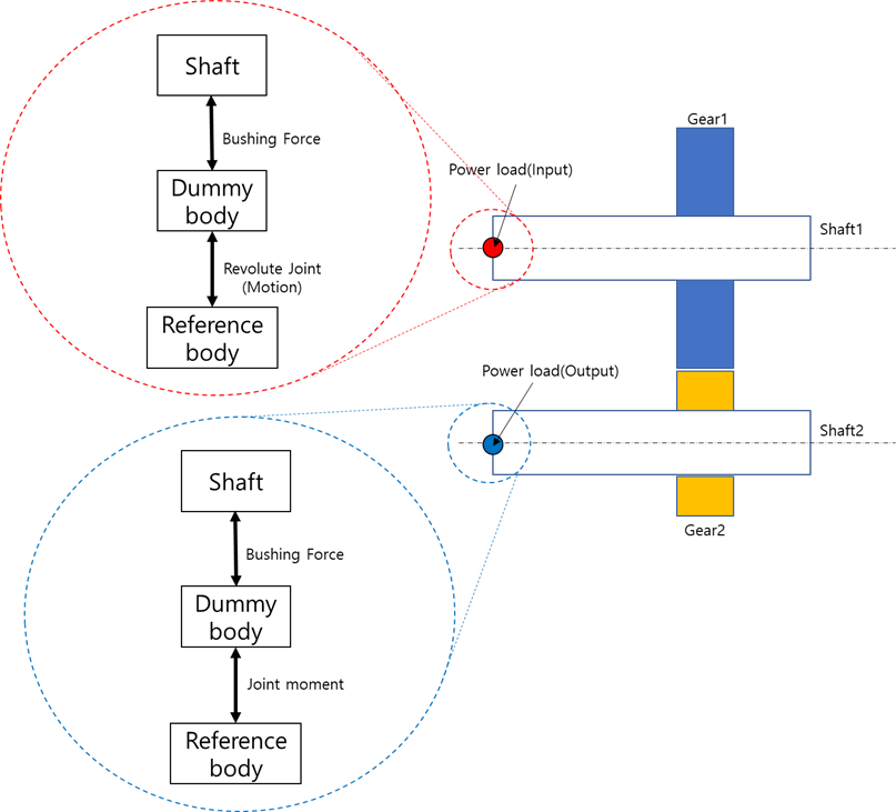
- Power Load
- Role
Set the power load role of the shaft. If you want to set this shaft as the input shaft of the power load, choose , otherwise choose to set this shaft as the output shaft of the power load. When is selected, the shaft set will have a no power load role.
- Remote Point
Set the power load input or output of the shaft. The motion or loading torque is applied to this point on the shaft.
- Connect with
Choose between , , , or .
- Attachments
- External Gears
Tabular data that defines which External Gear Sets are attached to this shaft, the object's location along the shaft, any relevant clearances, penalty values, and damping ratios.
- Internal Gears
Tabular data that defines which Internal Gear Sets are attached to this shaft, the object's location along the shaft, any relevant clearances, penalty values, and damping ratios.
- Planetary Gears
Tabular data that defines which Planetary Gear Sets are attached to this shaft, the object's location along the shaft, any relevant clearances, penalty values, and damping ratios.
- Double Pinion Planetary Gears
Tabular data that defines which Double Pinion Planetary Gear Sets are attached to this shaft, the object's location along the shaft, any relevant clearances, penalty values, and damping ratios.
- Crossed Helical Gears
Tabular data that defines which Crossed Helical Gear Sets are attached to this shaft, the object's location along the shaft, any relevant clearances, penalty values, and damping ratios.
- Rolling Bearings
Tabular data that defines which Bearings are attached to this shaft, the object's location along the shaft, any relevant clearances, penalty values, and damping ratios.
- Sliding Bearings
Tabular data that defines which Sliding Bearings are attached to this shaft, along with the reference position, distance, and start angle of each bearing.
- Unbalance Masses
Tabular data that defines unbalanced masses that are attached to this shaft by defining the mass, moment arm, base point, and distance of each.
When you select as the shaft type, use details to create rigid shaft bodies automatically. Beam shafts have following configurable details:
- Definition
- Status
Initially, this will be set to . Once the inputs are fully defined and the geometry is created is performed, this will be changed to . If the input changes later, this will be back to .
- Shaft Type
For beam shafts, this will always be set to .
- Coordinate System
Choose a CS to set the start position and rotational axis of the shaft.
- Rotate Axis
Choose a rotational direction for the shaft.
- Geometric Shapes
- Number of Sections
The total number of sections defined in this shaft. To change this number, add or delete shaft section in the Sections tabular data.
- Shaft Length
The total combined length of the sections defined in this shaft. To change this number, add or delete shaft sections in the Sections tabular data.
- Sections
Tabular data that defines the number of sections in the shaft, and the properties of each section. You may add and delete sections, and define the length, cross section, and relevant diameters of each section.
- Power Load
- Role
Set the power load role of the shaft. If you want to set this shaft as the input shaft of the power load, choose , otherwise choose to set this shaft as the output shaft of the power load. When is selected, the shaft set will have a no power load role.
- Base Point
Choose between or of the shaft. This choice will be used along with the Distance to determine the location of the Power Load on the shaft.
- Distance
The distance from the Base Point where the Power Load will be located on the shaft.
- Connect With
Choose between , , and .
- Moment Distribution Factor
Set the Moment Distribution Factor so that the sum of factor is 1. This value is used to compute the output torque of the shaft. See the formulas below for details.
- Reduction Ratio
The ratio by which the shaft reduces the input speed. This value is used to compute the output speed and torque of the shaft. See the formulas below for details.

- Efficiency
The efficiency percentage of the shaft, used to calculate the output torque. The maximum value of this setting is 100. See the formula below for details.

- Attachments
For each type of object, tabular data that defines which objects of that type are attached to this shaft and their details. Available object types are the same here as for Attachments of Flexible Shafts.
- Advanced
- Advanced Options
To manually set advanced options of the beam shaft, choose , otherwise choose to set advanced options automatically.
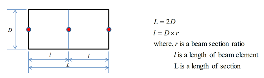
- Beam Section Ratio
The beam section ratio is used to calculate a length of unit beam element. The length of beam element can be calculated from beam section ratio as follows:
- Use Middle Element Reference Frame
Set to to define the element reference frame in the middle of the beam element. Set to to automatically calculate the location of the element reference frame.
- Material
- Assignment
Choose a material that will be assigned to the body objects after the geometries are imported.
The Housing object allows you to select an existing housing body and to define the attached gears and bearings.
- Definition
- Status
Initially, this will be set to . Once the inputs are fully defined and the geometry is created is performed, this will be changed to . If the input changes later, this will be back to .
- Scope
- Scoping Method
Choose between and .
- Geometry
If you chose as the scoping method, choose flexible body objects in the geometry of the model, then press to add those objects to the Geometry of the Shaft object.
- Named Selection
If you chose as the scoping method, choose a predefined named selection object of flexible objects from the drop-down menu, then press to add the objects in that selection to the named selection of the Shaft object.
- Attachments
- External Gears
Tabular data that defines which External Gear Sets are attached to this housing, the object's location, any relevant clearances, penalty values, and damping ratios.
- Internal Gears
Tabular data that defines which Internal Gear Sets are attached to this housing, the object's location, any relevant clearances, penalty values, and damping ratios.
- Rolling Bearings
Tabular data that defines which Bearings are attached to this housing, the object's location, any relevant clearances, penalty values, and damping ratios.
- Unbalance Masses
Tabular data that defines unbalanced masses that are attached to this housing by defining the mass, moment arm, base point, and distance of each.
When housings are not used, Drivetrain Assembler enables you to finalize the system assembly.
- Definition
- Status
Initially, this will be set to . Once the inputs are fully defined and the geometry is created is performed, this will be changed to . If the input changes later, this will be back to .
- Reference Body
Use to set the parent part of drivetrain system. All reaction forces of each mounting constraint are applied to the reference body.
- Reference Body Type
Select reference body type among “Ground” / “Body” / “Remote Point”
- Connect to Shaft
- Translational K Coefficient
To set the translational stiffness value as a constant value related to displacement-force in bushing force, choose
Otherwise, choose (Displacement-Force Spline) to set the translational stiffness value as a variable-value displacement-force in bushing force. Also, when choosing , set the 3 the spline data about the , , and axis, and use a . Refer to the figure below for bushing force.
- Translational C Coefficient
To set the translational damping value as a constant value related to velocity-force in bushing force, select .
Otherwise select (Velocity-Force Spline) to set the translational damping value as variable-value velocity-force in bushing force. Also, when selecting , set the 3 spline data about the , , and axis. Refer to Figure 3.23: Bushing Force for bushing force.
- Rotational K Coefficient
To set the rotational stiffness value as a constant value related to displacement-force in bushing force, select .
Otherwise select (Displacement-Force Spline) to set the rotational stiffness value as variable-value displacement-force in bushing force. Also, when selecting , set the 3 spline data about the , , and axis, and use a . Refer to the figure below for bushing force.
- Rotational C Coefficient
To set the rotational damping value as a constant value related to velocity-force in bushing force, select .
Otherwise select (Velocity-Force Spline) to set the rotational damping value as variable-value velocity-force in bushing force. Also, when selecting , set the 3 spline data about the , , and axis. Refer to the figure below for bushing force.
- Pre-Load
To set a pre-load at the translational axis in bushing force, select . Also, set the pre-load value data about the , , and axis.
Otherwise select to set no pre-load in bushing force.
- Pre-Moment
To set a pre-torque (moment) at the rotational axis in bushing force, select . Also, set the pre-torque value data about the , , and axis
Otherwise select to set no pre-torque in bushing force.
- Use Static Bushing
Used only to enable static bushing during static analysis. For the neutral equilibrium problems, such as contacts, free falling, and running vehicle, this option is very useful to find a static equilibrium position successfully.
If the bushing is defined between the ground and a sliding body with a stiffness coefficient in the sliding direction, this will help the solver achieve numerical stability during the static analysis.
- Bearing Assembly Information
- Bearings
- Reference Penalty
Use to set the penalty for the clearance. Refer to Figure 3.24: Reference Damping Ratio.
- Reference Damping Ratio
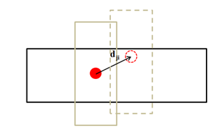
Set the damping ratio for clearance. The clearance force is created when the component is added to the shaft set or housing to represent the connection between each component. The clearance force is split into axial and radial forces.
It is computed as:

where, k is a penalty, dji is the relative displacement between the inner and outer raceways of the bearing,cl is a clearance, and c is the proportional damping ratio.
Drivetrain Driving Scenario enables you to define the loading to apply to the drivetrain system.
Before using this, you must designate each shaft as an input or output shaft using the Power Load setting for each shaft object. To evaluate output torque at each output shaft, Input Power and Max Moment (the maximum torque on the shaft) values of the power source are also required. The rest of the inputs are used for defining the rotational motion to be imposed on the input shaft.
- Input
- Input Shaft
Choose a Shaft object that has been defined with an Input Type with the role of .
- Input Speed Type
Choose between , , and . If you choose , the input speed will be the opposite direction relative to the type. If you choose , you will also need to define a Spline object to represent time versus rpm directly.
- Rotating Direction
Specify whether the direction of accelerated rotation relative to the axis of the input shaft is or .
- Input Power Type
Choose between and . If you choose , you will also need to define a Spline object to represent rpm versus power.
- Input Power
Specify the constant power value of the power source that is input to the drivetrain system.
- Max Moment
Specify the maximum torque value of the input power source. Usually, power and maximum torque can be input through the owned specifications of the desired motor or engine. This value will be used for reporting output torque for each output-type shaft.
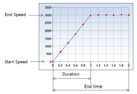
- Duration
Specify the time range during which acceleration or deceleration motion will be applied.
- Start Speed
Specify the rotating speed of the power load at the beginning of simulation.
- End Speed
Specify the rotating speed of the power load after the acceleration/deceleration is complete and a constant speed has been maintained.
- Interpolation Type
Choose between and . If you choose , you will need to define the number of spline points using Number of Interpolation Data.
- Number of Interpolation Data
Specify the number of the "time versus rpm spline" points to internally create using the given inputs.