


Motion helps to automatically model a system with patterns, such as a chain, track, belt or a general system composed of many similar repeated parts. This toolkit can generate multiple contacts and multiple connections among the components easily and quickly. It also enables you to modify properties related to contacts and connections.
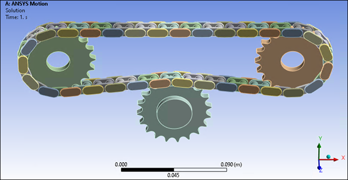
Create a repeated system by defining the required objects and then associating them with a Links Assembler object. To generate the system, right-click the Links Assembler object and choose from the context menu.
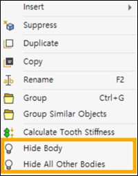
The bodies created by Links Toolkit objects can be hidden or displayed by right-clicking the object in the tree and selecting or (see Figure 2.8: Body Display Options).
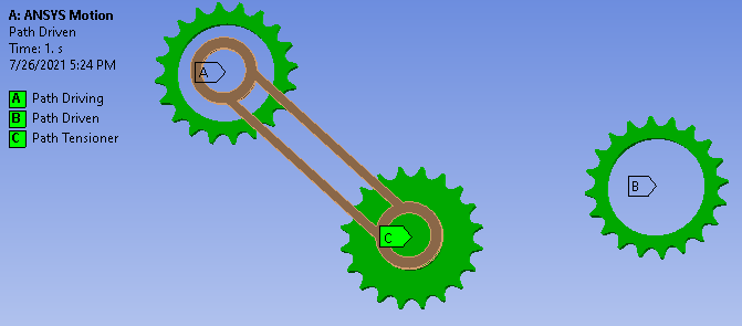
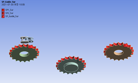
The Path object is the key entity that will be wrapped by the linked system. Path objects are typically sprockets, rollers, and similar geometries.
For the connection with the segments, a geometry scoping is required. Also, contact regions are needed to model contact with segments.
Path objects have the following details:
- Scoping Method
Choose between and methods for selecting the object in the geometry that will define this Path object.
- Geometry / Named Selection
If you chose the scoping method, select this field, then choose an object in the geometry of the model, and press to add that object to the Geometry of the Path object.
If you chose the scoping method, choose a predefined named body to add that object to the Named Selection of the Path object.
- Contact Regions
Tabular data that defines the Named Selections that contact segment faces.
- Path Transform
Tabular data. The coordinate system defines the rotation center point and rotation direction of each path. The rotation center points of each path define the center line where the segment is eventually created. The rotation axis of the path must be defined as the Z-axis of the coordinate system.
- Direction
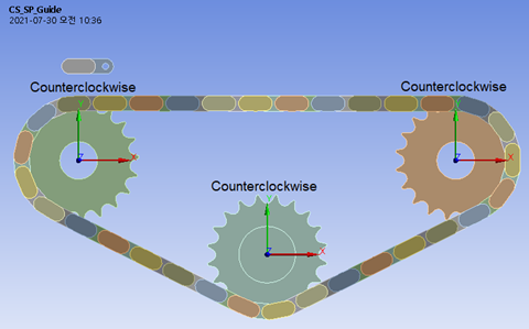
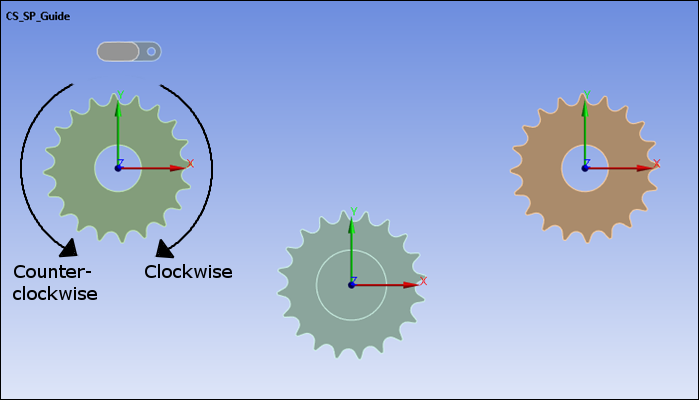
If the direction of the rotation axis of the path is determined by the Path Transform, the winding direction is determined based on the +Z direction. is the default direction because it follows the right-hand rule. When winding in the opposite direction, select .
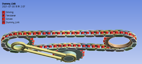
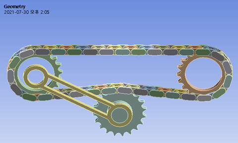
The figures below show the addition of the placed segments (chain) around the Path objects, featuring clockwise and counterclockwise tensioners, respectively:
Figure 3.31: Path Transform Coordinate System of Path Objects and Direction with Placed Segments (Clockwise Tensioner)
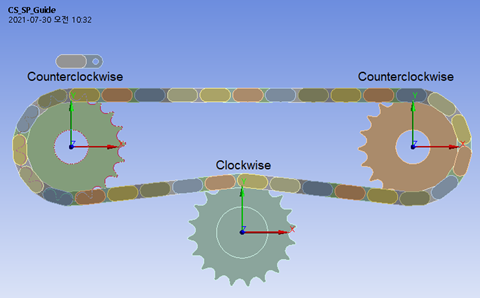
Figure 3.32: Path Transform Coordinate System of Path Objects and Direction with Placed Segments (Counterclockwise Tensioner)
- Radius
The path's distance of the from the center of rotation of the Path object. Depending on the shape of the path, the input value is divided into two types. In the case of roller shape, input the length in contact with the segment. In the case of a toothed shape such as a gear or sprocket, input the
Pitch Circle Radiusvalue. TheRadiusis a value used in the formula for winding Links with the segment'sHeight.- Treat as Sprocket
Choose from the drop-down menu to define this Path object as a toothed sprocket such as a gear.
Choose from the drop-down menu to define this Path object as a smooth path such as a roller.
This represents the effect of the gap when a Path is wrapped by Segments. If this is , the original value of Segment length is used when the position and orientation of a Segment is calculated. If this is , a modified value of Segment length is used when the position and orientation of Segment is calculated. The modified value of Segment length is always used between Paths.
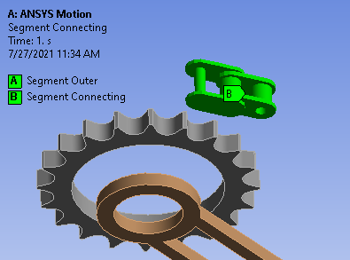
The Segment object are the wrapping entity in the system.
When segments are assembled, the scoped geometries are duplicated. The initial scoped segments don't affect Links modeling and are not used in the solution.
Segment objects have the following details:
- Scoping Method
Choose between and methods for selecting the object in the geometry that will be defined by this Segment object.
- Geometry / Named Selection
If you chose the scoping method, select this field, then choose an object in the geometry of the model, and press to add that object to the Geometry of the Segment object.
If you chose the scoping method, choose a predefined named body to add that object to the Named Selection of the Segment object.
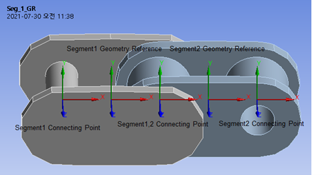
- Geometry Reference
A predefined base Coordinate System object that represents a segment. If the coordinates are not defined properly, the links may not wrap in the desired shape.
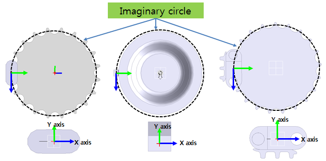
The X-Axis of the Coordinate System is the tangential vector of an imaginary circle of path. Set the +X direction to the direction in which the next segment is linked. The Y-Axis of the Coordinate System is a normal vector to the direction of the center of the imaginary circle. The direction of the Z axis of the coordinate system is the direction in which the segment rotates or bends.
- Segment Length
The length of the segment. This is sometimes expressed as the distance between adjacent segments on both sides. So, given symmetrical geometry, adjacent segments are created at half the length from the Geometry Reference.
When the connection between segments is a type of joint, the Segment Length determines the location where the connection is created.
- Segment Height
Segment Height represents the distance from the Geometry Reference to the contact point. Segment Height1 represents the distance to the contact point in the positive-Y direction of the Geometry Reference. The Path used is counter-clockwise. Segment Height2 represents the distance to the contact point in the negative-Y direction of geometry reference. The Path used is clockwise.
- Auto Connection
Choose either or from the drop-down menu. If you choose , you will also need to define a Scoping Method and for the Reference and Mobile connection faces.
Setting Auto Connection to is useful when the connecting point is in line with the Segment Geometry Reference and there is no need to define the connecting Coordinate System in the Transform List.
If you choose , you will also need to define a Transform List.
- Transform List (Auto Connection is User Defined )
Tabular data that defines the Coordinate Systems that are part of this segment's connections to the other Segments in the system.
- Contact Regions
Tabular data that defines the Named Selections that are contact regions within the segment.
- Scoping Method (Auto Connection is Program Controlled)
Choose between and methods for selecting the regions in the geometry that will be defined as contact regions for the Auto Connection.
- Geometry / Named Selection (Auto Connection is Program Controlled)
If you chose the scoping method, select this field, then choose a region in the geometry of the model, and press to define that region as a contact for the Auto Connection.
If you chose the scoping method, choose a predefined Named Selection to define that region as a contact for the Auto Connection.
A Links Assembler object can assemble segments so that they wind the selected path objects in the defined order.
In the case of using multiple types of segments, the positioning pattern can be defined by the user. By default, segments are repeated in the selected order.
Segments are created when the action is selected from the object's context menu.
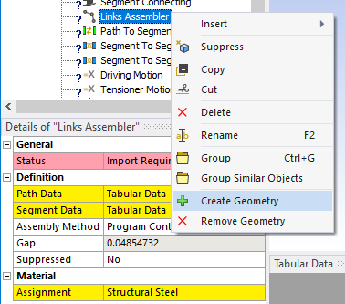
Links Assembler objects have the following details:
- Path Data
Tabular data that defines a Path to be wound by the Segments. When defining a Path, the winding direction changes according to the order of the Path Data. In addition, you can review previously defined Path information.
- Segment Data
Tabular data that defines the dimensions of the Segment's component objects.
- Assembly Method
Choose from , , and . If you choose , you will also need to define the Number of Segments and whether or not the path is an Open Loop. If you choose , you will need to define Tabular Data to define how to choose segments while assembling the path.
- Gap
Spacing between the segments in the link path.
A Path Follower object assembles selected segments along right-hand-side and left-hand-side predefined Curvesets. It can be used, for example, in roller-coaster or train applications.
Define a curve that represents the target path. This will serve as a middle curve between two curvesets that form the left and right rail geometries.
When you choose the action from the object's context menu, Motion creates segments to follow the curvesets.
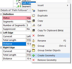
Path Follower objects have the following details:
- Segments
The segments to duplicate.
- Number of Segments
Number of segments to generate.
- Left Edge
- Curveset
The left-side Curveset.
- Distance
Specifying the start point of the left-side Curveset to compute the location where the first segment will be placed.
- Right Edge
- Curveset
The right-side Curveset.
- Distance
Specifying the start point of the right-side Curveset to compute the location where the first segment will be placed.
To constrain the segments with a curveset, define a Segment on Path object.
The Path To Segment Contact object creates contacts internally between the selected path and segment.
M × N × n contacts
will be created where:
Mis the number of the selected named selections in Path List for ContactNis the number of selected named selections in Segment List for Contactnis the number of imported segment geometries
Path to Segment Contact objects have the following details:
- Links Assembler
The name of the Links Assembler object that will process this object. All objects that are part of the same repeated system should be associated with the same Links Assembler.
- Path List for Contact
Tabular Data that selects the path faces for contact with segments.
- Segment List for Contact
Tabular Data that selects the segment faces for contact with paths.
The Segment To Segment Connection object creates a bushing joint between adjacent segments, internally.
The target body of the connection is specified through Segment and Segment Face, and the transformation of the connection is specified using Segment Transform.
Segment to Segment Connection objects have the following details:
- Links Assembler
The name of the Links Assembler object that will process this object. All objects that are part of the same repeated system should be associated with the same Links Assembler.
- Type
The type of connection between the two bodies. Choose one, or . Based on your choice, you will need to define further details.
- Joint Type (Applicable to Joints only)
Choose a Joint Type from the drop-down menu. These types and their properties are described in Joints.
- Bushing Stiffness Worksheet (Applicable to Joints only)
Tabular data that describes the stiffness forces and moments of the joint.
- Bushing Damping Worksheet (Applicable to Joints only)
Tabular data that describes the damping forces and moments of the joint.
- Reference Segment (Applicable to Joints and Contacts)
Choose the segment that will be the base segment of the connection.
- Reference Segment Face (Applicable to Joints and Contacts)
This option is visible when the Segment’s Auto Connection option is set to . Choose the Named Selection that will be the reference of the geometry connection.
- Reference Segment Transform (Applicable to Joints only)
This option is visible when the Segment’s Auto Connection option is set to . Choose the Coordinate System that will be the reference of the connection.
- Mobile Segment (Applicable to Joints and Contacts)
Choose the segment that will be the mobile segment of the connection.
- Mobile Segment Face (Applicable to Joints and Contacts)
This option is visible when the Segment’s Auto Connection option is set to . Choose the Named Selection that will be the mobile face of the geometry connection.
- Mobile Segment Transform (Applicable to Joints only)
This option is visible when the Segment’s Auto Connection option is set to . Choose the Coordinate System that will be the mobile segment of the connection.
The Segment Inner Connection object creates a contact or various type of joint between the specified segment geometries internally. This enables you to model the relationship between geometry when a Segment object has multiple geometries.
Segment Inner Connection objects have the following details:
- Links Assembler
The name of the Links Assembler object that will process this object. All objects that are part of the same repeated system should be associated with the same Links Assembler.
- Target Segment
Choose the name of the Segment object to define the connection between the internal bodies of the Segment.
- Type
The type of connection between the two bodies. Choose one, or . Based on your choice, you will need to define further details.
- Connection Type (Joint)
If you chose a Type of , choose the type of joint connection: or .
If you choose a Connection Type of , you will also need to define a Reference Body, Reference Body Face, and Reference Body Transform.
- Joint Type (Joint)
Choose a Joint Type from the drop-down menu. These types and their properties are described in Joints.
- Bushing Stiffness Worksheet (Applicable to Joints only)
Tabular data that describes the stiffness forces and moments of the joint.
- Bushing Damping Worksheet (Applicable to Joints only)
Tabular data that describes the damping forces and moments of the joint.
- Reference Body (Applicable to Body-Body Joints and Contacts)
Choose a reference body for the joint or contact.
- Reference Body Face (Applicable to Body-Body Joints and Contacts)
Choose the face of the selected reference body where the inner connection will be made.
- Reference Body Transform (Applicable to Body-Body Joints only)
Choose a transform type for the selected face of the reference body.
- Mobile Body (Applicable to Joints and Contacts)
Choose the mobile body for the joint or contact.
- Mobile Body Face (Applicable to Joints and Contacts)
Choose the face of the selected mobile body where the inner connection will be made.
- Mobile Body Transform (Applicable to Joints only)
Choose a transform type for the selected face of the mobile body.
When using a Path Follower object, the Segment On Path object enables you to constrain a segment with a curveset. Define a Segment On Path for each face to connect segments along the target path.
Segment On Path objects have the following details:
- Path Follower
The Path Follower object.
- Clearance
The constraint clearance.
- Stiffness Scale
Used to define Program Controlled and a Stiffness Scale Factor (all segments use the same scale factor).
- Reference
- Curveset
The right/left curveset.
- Coordinate System
Used to locate the path location to connect with the segment.
- Mobile
- Segment
The segment to constrain.
- Named Selection
The named selection that contains the segment faces to constrain.
- Coordinate System
Used to locate the segment location to connect.
Insert a Soil Interaction object to define the behavior of a predefined or custom soil type and how it interacts with the other components of the system. This is useful for modeling the behavior of vehicles that use treads for ground traction instead of tires.
Soil Interaction objects have the following details:
- Scoping Method
Choose between and methods for selecting the contacts that will interact with the soil.
- Geometry / Named Selection
When using the scoping method, select objects in the geometry of the model, and click to add those objects to the Geometry of the Soil Interaction object.
When using the scoping method, choose a predefined named body to add that object to the Named Selection of the Soil Interaction object.
- Vertical Direction
Choose an object name from drop-down menu to indicate which direction should be modelled as the vertical direction towards the soil.
- Target Links Assembler
The name of the Links Assembler object that will create the linked system that interacts with the soil. If Target Links Assembler is set to , you can choose general bodies in List of Action Entity.
- List of Action Entity
Tabular data that defines the soil interaction in terms of named bodies, contact transforms, shapes, area length, area width, number of contact points along the length, and number of contact points across the width of the linked system.
- Soil Type
Choose a soil from the drop-down menu to define the type of soil for the interaction, or choose to define a custom soil type by its physical properties.
- Damping Ratio
This ratio is used in the calculation of the damping coefficient for soil interaction (must be greater than or equal to 0). For more information see Soil Interaction Entity Properties in the Motion Preprocessor User Guide.
- Boundary Sinkage
Used to mitigate the effect of damping forces for soil interaction (must be greater than 0).
For more information see Soil Interaction Entity Properties in the Motion Preprocessor User Guide.