Contacts enable you to connect flexible and rigid bodies. Different contact types are used to define the behavior of the connection.
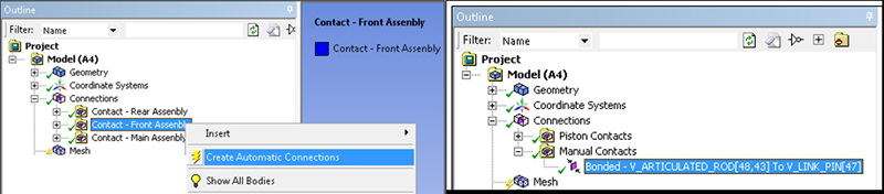
Contacts may be defined automatically or created manually. Contact pairs can be automatically detected and generated in Mechanical when you first attach geometry. If a required contact is not detected and defined automatically, you will need to create the contact conditions manually.
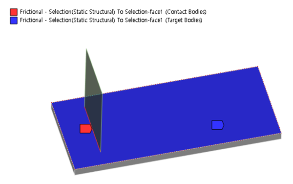
When creating contact between a rigid body and a flexible body, select the flexible body as the Contact body and the rigid body as the Target body. If you do not create a Contact Properties object, the parameters are set to default values.
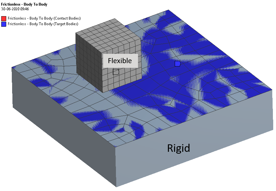
Figure 2.29: Equivalence between Motion in Workbench and Standalone Motion
| Motion Standalone | Motion in Workbench | |
|---|---|---|
| Base (Contact) | Rigid (Faceset) | Flexible Behavior |
| Action (Target) | FE (Patchset) | Rigid Behavior |
Contact in Workbench corresponds to the Base geometry in the Standalone Preprocessor.
Target in Workbench corresponds to the Action geometry in the Standalone Preprocessor.
A Patchset creates a group of triangular or rectangular patches on an FE body to define contact.
A can represent the contact surface on a rigid body.
You can select and geometry types for contacts and may also select geometry types to connect circular beams to faces. Some combinations of contact are also supported for non-beam flexible bodies (see Defining Edge Contacts). , , , and geometry types may not be selected for contact.
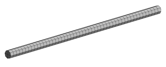
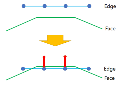
You may select an edge on a beam body for a Contact Region in a Motion analysis. This beam body must have a circular cross section. In this case, based on the R dimension of the beam cross section properties, the solver uses a virtual shape of hexahedrons surrounding the middle beam line to represent the real contact surface (see figure below).
Limitation
Partial selection of edges for contact is not supported. You may therefore need to split the beam body to use for contact.
To use Edge Contact for a Contact Region in a Motion analysis, the contact (base) must always be an edge. The target body can be an edge or face.
The following face and edge combinations are supported for Edge Contact:
Table 2.5: Support for Edge Contact
| Contact - Edge (Flexible) | Contact - Edge (Rigid) | |
|---|---|---|
| Target - Face (Flexible) | Supported | Not Supported |
| Target - Face (Rigid) | Supported | Not Supported |
| Target - Edge (Flexible) | Supported | Not Supported |
| Target - Edge (Rigid) | Not Supported | Not Supported |
Contact Point Detection Algorithm
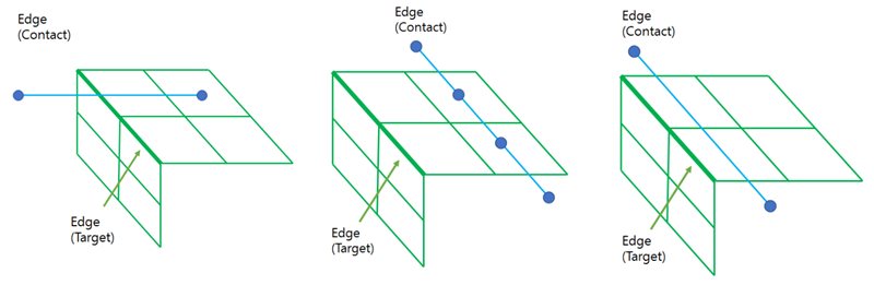
Edge to Face
Consists of a Vertex-to-Patch search using an FE Node belonging to the Edge as the Vertex, and an Element face belonging to the Face as the Patch (if the element is of high order, the mid-node is also used as a vertex).
Contact point example:
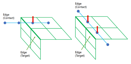
Edge to Edge
Consists of a Vertex-to-Patch search using an FE Node belonging to the Contact Edge as the Vertex, and an Element face including the Target Edge as the Patch (if the contact edge element is of high order, the mid-node is also used as a vertex).
Contact point example:

There are 4 types of Contact:
- Bonded
Supports only Nodal flexible bodies for both Contact and Target.
- No Separation
Supports only Nodal flexible bodies for both Contact and Target.
- Frictionless
Supports all types of bodies.
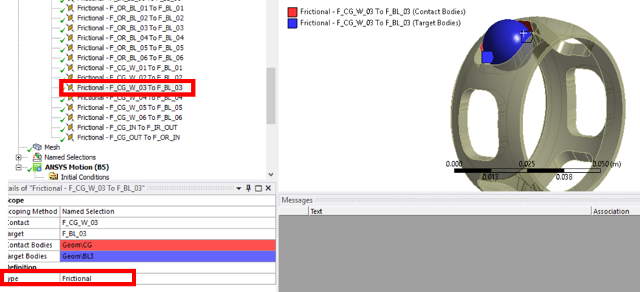
- Frictional
Supports all types of bodies.
Contact Regions of type Bonded or No Separation are supported only for Nodal flexible bodies .
The contact type for the solver is determined by the Body Flexibility and Surface Type selected in the contact properties for / contacts.
| Contact Type in Workbench | Select Body | Surface Type | Solver Contact Type |
|---|---|---|---|
| Frictional / Frictionless | Rigid + Rigid | Multi-Point | General Contact |
| FE + Rigid | Multi-Point | ||
| FE + FE | Multi-Point | ||
| Rigid + Rigid | Surface | RTR 3DContact | |
| FE + Rigid | Surface | FTR 3DContact | |
| FE + FE | Surface | FTF 3DContact | |
| Bonded / No-Separation | Any | NA | Tie Constraint |
In Workbench, Bonded and No Separation contact are represented internally as Tie Constraints and are only supported between FE Nodal bodies.
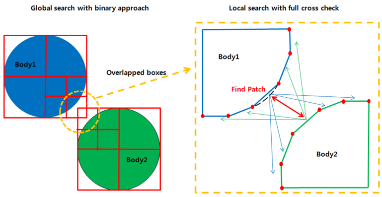
The detection method executes two searches to find contact pair candidates. The first is a global search and the other is a local search. If the bounding boxes in the global search overlap, those boxes are divided to sub-domain boxes to be inspected for overlapping contact patches. The solver then uses a local search to find overlapping patches (see below).
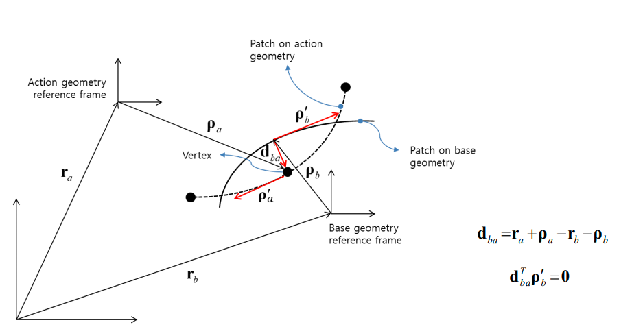
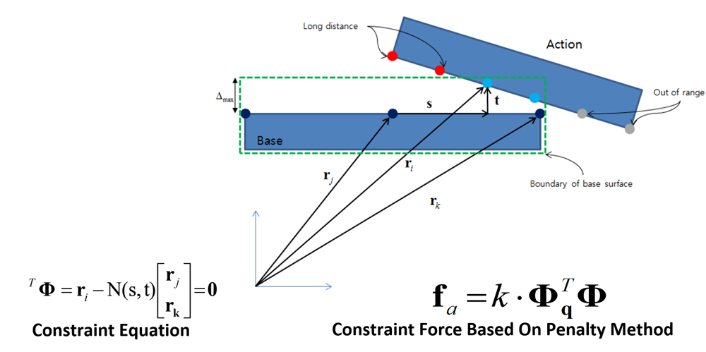
If the relative displacement dba is perpendicular to the tangent direction at a point on the base surface, the point can be considered a contact point, as shown below.
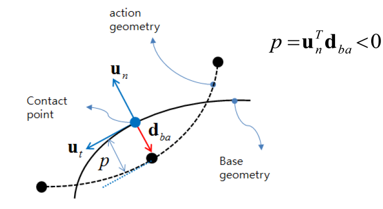
The contact penetration p can be calculated from the relative displacement and normal direction, as shown below.
Frictional or Frictionless Contact
Motion uses a penetration method to determine friction at the contact point.
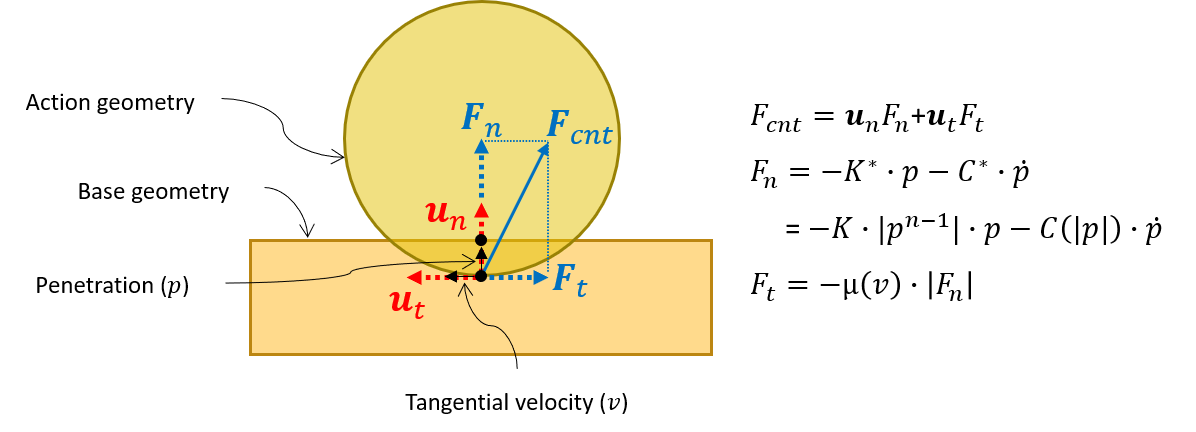
Where:
Fcnt : Contact force
Fn : Normal force of Fcnt
Ft : Friction force of Fcnt
K : Stiffness coefficient
C : Damping coefficient
p : Penetration
n : Exponent of penetration
 : Penetration velocity
μ : Friction coefficient
v : Tangential velocity
Bonded or No Separation Contact
The nodes on the action surface are tied to each corresponding point on a base surface. Tie contact constrains full DOFs of each node relative to the other surface. See Tie Contact in the Motion Preprocessor User Guide for more information.
Insert a Contact Properties object to specify additional contact characteristic values. This can be applied to a set of Contact Region objects whose type is or .
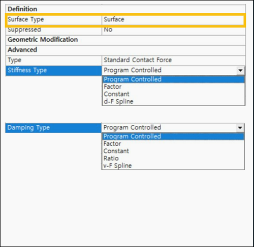
Surface Type
If Surface Type is set to , and the contact is defined between a rigid and a flexible body (as the Target and Contact bodies, respectively), the base and action are flipped internally during analysis. With this option, Stiffness Type can be set to , , or . See available options in Figure 2.42: Available Contact Properties: Surface Type = Surface.
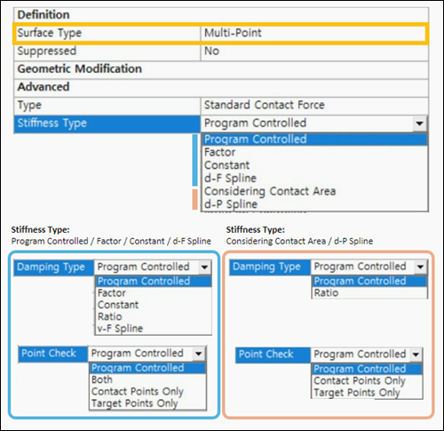
If Surface Type is set to , Stiffness Type has additional options for and . See available options in Figure 2.43: Available Contact Properties: Surface Type = Multi-Point.
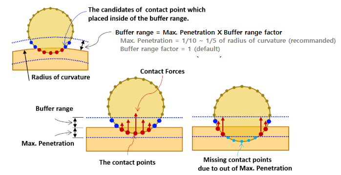
Maximum Penetration and Buffer Range
Usually, Max. Penetration is set first and Buffer Range Factor does not need to be changed. The purpose of the buffer range is to detect contact candidates before the contact has begun. If the model has contact between fast-moving bodies, a larger buffer range is required to detect this. To increase the buffer range, set Buffer Range to , and Buffer Range Factor to a larger value.
Note: Max Penetration can be defined for both the Contact and Target bodies, allowing different conditions for each body surface.
The Max. Penetration setting determines buffer range as follows:
Only the objects within max. penetration and the buffer range are considered when calculating contact.
Buffer range = Max. Penetration x Buffer Range Factor (default =1).
Too large a value may cause contact analysis to run with poor performance.
Too small a value may cause problems with missed contact.
A value of 1/10 ∼ 1/5 of the radius of curvature is recommended.
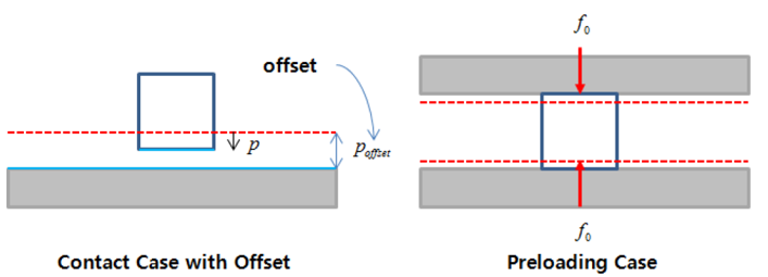
Offset
Offset is used to offset the Contact or Target surface. When one body is enveloped by another body, use a small offset to help establish contact and improve numerical stability in the Motion solver.
Stiffness
You can choose a contact Stiffness Type and Coefficient Factor from the Advanced properties of a Contact Properties object.
- Stiffness Type
Use to set the stiffness coefficient type: , , , , or .
The option is recommended when you need to increase contact stiffness in proportion to the increase in the contact area. If you select , available Stiffness Evaluation Types are as follows:
: the stiffness per contact area is defined by the Young's modulus, Poisson's ratio, and the Thickness of Contact Surface, where the material information set in the body is retrieved automatically. The stiffness per contact area is inversely proportional to the Thickness of Contact Surface. Refer to Intermittent Contact Force in the Motion Theory Reference for more information.
: the stiffness per contact area is defined by user input.
Note that the size of the facets and patches must be small enough, otherwise the area contact option can cause system instability or an incorrect solution. For more information see General Contact Properties in the Motion Preprocessor User Guide.
When (Displacement-Force Spline) or (Displacement-Pressure Spline) is selected, contact spring force can be defined with a predefined spline for Penetration-Force or Penetration-Pressure curves. When is selected as the stiffness type, the damping type is usually defined as .
When or is selected as the Stiffness Type, the Damping Type is always defined as .
- Stiffness Coefficient Factor
A low stiffness coefficient makes for good numerical convergence, but allows large contact penetration.
A high stiffness coefficient reduces penetration, but can cause contact noise and bad numerical convergence. For more information see Spring forces for normal force in the Motion Theory Reference.
Damping
Set Damping Type to , , or .
Selecting means that the Damping Coefficient is used as a scale factor for the contact Stiffness Coefficient currently being applied.
When (Velocity-Force Spline) is selected, contact damping force can be defined using a predefined spline.
Usually, a maximum damping coefficient value in the range of 1E-3 ∼ 1E-6 times the stiffness coefficient value is used.
Note: If Stiffness Type is set to or , only the and options are available for Damping Type.
Bounce Off Damping Factor
The Bounce Off Damping Factor is intended to prevent excessive adhesion when the contact surfaces move outside the penetration range. It only affects the solution when an object is moving away from the contact surface (penetration velocity is negative) and has no effect when it is approaching or stationary. The limit of the adhesive force is determined using a factor proportional to the spring force component of the contact normal force (see Figure 2.46: Normal force calculated using bounce off damping factor).
This factor can be specified as a value between 0 and 1 as follows:
When set to 1, no damping force is generated as the contact surface moves away.
When set to 0, the damping force is limited by the spring force value of the contact normal force. So, in this case the sum of the normal forces can be zero, even though the bodies are in contact.
This can be expressed as shown in the formula and graph below.

Where fn is the normal force, Rb is the bounce off damping factor, and fs is the spring force component of the contact normal force.

Enable this option by setting Use Bounce Off Damping Factor to and then specify a numerical Bounce Off Damping Factor to give different damping values depending on the state of contact. Values in the range 0 to 1 are supported, as described above.
Note: This damping factor is not used if the Sliding Contact Option (see below) is selected.
Max. Step Size
This property sets the modification factor for the step size used during contact detection.
Contact between two bodies is imminent when their buffer ranges start to overlap. The solver therefore monitors this condition and when overlap is detected, it reduces the step size by the specified factor (usually smaller than 1). This avoids the risk of the bodies passing through each other without making contact, due to a large change in displacement between two time steps.
If you do not specify a factor, it will default to a value of 1, meaning that there will be no modification to the step size when buffers ranges start to overlap.
Use Increment Time
If this option is set to (default = ), the Increment Time parameter is used and the applied contact force Fcnt is calculated as follows:

Fcnt.applied is the contact force when using the Use Increment Time option.
Fcnt.actual is the contact force without the Use Increment Time option.
This is useful if you need to gradually increase the contact force, such as in a shrink-fit simulation.
Point Check
This option is only exposed when Surface Type is set to . You can use this to set one of the following options for finding contact points:
- Program Controlled
This option uses (see below) when Stiffness Type is set to , , , or . If Stiffness Type is set to or , it uses .
- Contact Points Only
Only the nodes on the Contact surface are examined.
- Target Points Only
Only the nodes on the Target surface are examined.
- Both
This option is exposed when Stiffness Type is set to , , or . The nodes on both Contact and Target surface are examined.
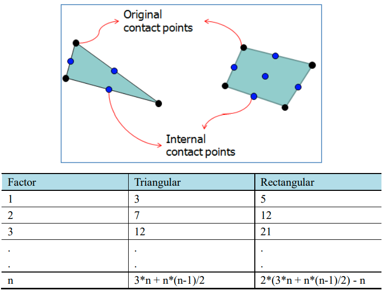
Factor for Internal Point
This parameter is exposed when the Use Factor for Internal Point option is set to and it generates additional internal contact points on a patch. This is useful for models where it is otherwise impossible to increase the number of contact points, such as with a Patchset on an FE body. This is a good option when you get a poor contact solution due to a rough mesh. The number of additional internal contact points can be determined as shown in the table below.
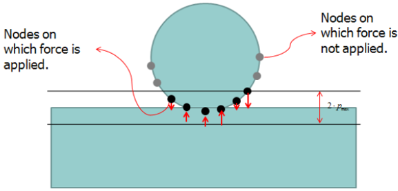
Sliding Contact Option
In sliding contact, contact force is only generated at nodes within the maximum penetration range, as shown in the figure below. If the penetration is greater than zero, a repulsive force is generated. The Sliding Contact Option reduces the repulsive force by adding opposing forces on the nodes located in the penetration area. This can improve the stability of time integration under higher contact forces and is useful in reducing chattering effects in sliding contact between two bodies.
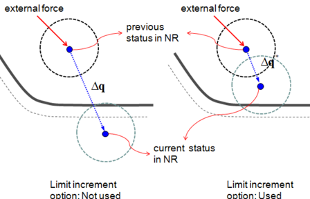
Use Limit Increment in NR
If the Newton-Raphson (NR) increment is larger than the maximum penetration, the Motion solver cannot detect contact. However, if the Use Limit increment in NR option is selected, the solver can limit the solution to the specified value. Since using this option decreases the integration step size, the solving time may be longer.