


The FE Shaft Set Designer property view of the consists of the General tab and Component Analysis tab.
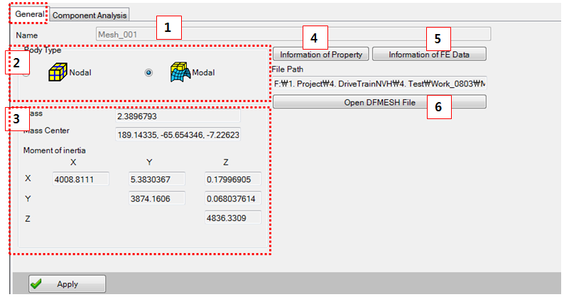
Figure 14.81: Parameters in the FE Shaft Set Designer General tab
| Parameter | Description |
| 1. Name | Show the dfmesh file name for a FE Shaft Set. |
| 2. Body Type | Use to select the body type. Nodal FE Body and Modal FE Body can be selected. Modal FE body has been widely used to represent the FE shaft. |
| 3. Mass information | Show the mass information of Shaft Set. |
| 4. Information of Property | Use to show the information of property for the FE shaft. |
| 5. Information of FE Data | Use to show the information of the finite element for the FE shaft. |
| 6. Open DFMESH File | Use to open the dfmesh file for the Shaft Set. |
Component analysis solves the static equilibrium and eigenvalue problem of the Shaft Set. The deformation, mode and natural frequency of Shaft Set including the gear and bearing can be tested before confirming the Shaft Set shape.
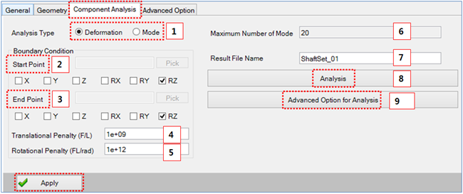
Figure 14.83: Parameters in the Component Analysis tab
| Parameter | Description | Dimension |
| 1. Analysis Type | Use to select the analysis type of "Deformation" or "Mode". When the "Deformation" is selected, the statics analysis is carried out. When the "Mode" is selected, the eigenvalue analysis is carried out and the mode and natural frequency of the Shaft Set can be analyzed in the post processor. | N/A |
| 2. Start point | Use to set a RBE corresponding starting point of the Shaft Set by using General Picker and the boundary condition which will make the constrained equation to the ground. | N/A |
| 3. End point | Use to set a RBE corresponding end point of the Shaft Set by using General Picker and the boundary condition which will make the constrained equation to the ground. | N/A |
| 4. Translational Penalty(F/L) | Use to set the translational penalty of the boundary condition. | Force/Length |
| 5. Rotational Penalty(F/rad) | Use to set the rotational penalty of the boundary condition. | Force*Length/Radian |
| 6. Maximum number of mode | Use to set the number of modes for the "Mode" analysis type. | N/A |
| 7. Result File Name | Use to set the result file name. The result is created in the new folder under the current subsystem folder. | N/A |
| 8. Analysis | Use to start the simulation. | N/A |
| 9. Advanced option for Analysis | Use to set Simulation Configuration Parameters. | N/A |