


General
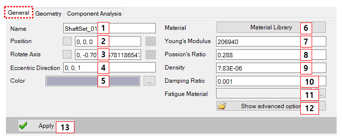
Figure 14.72: Parameters in the Simple Shaft Set designer General tab
| Parameter | Description | Dimension |
| 1. Name | Use to set the name of Shaft Set. | N/A |
| 2. Position | Use to set a starting point of the simple Shaft Set by the Point Picker. This becomes a base marker position of the 1stbeam element. This parameter can be parametrized by design point, design frame. | Length |
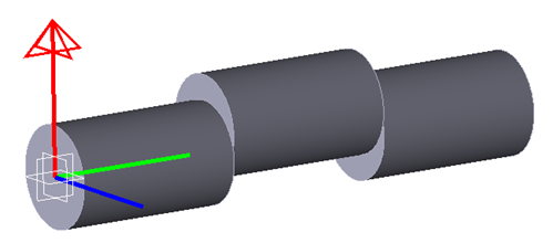
| 3. Rotate Axis |
Use to set the rotational direction by the Direction Picker. The default value can be defined from the direction of the Shaft Set. This parameter can be parametrized by z axis vector of design frame. | N/A |
| 4. Eccentric Direction |
Use to set the eccentric direction in the global reference frame for crank Shaft Set.
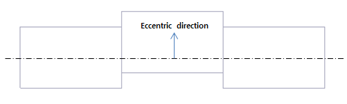
| N/A |
| 5. Color | Use to set the color of the Shaft Set. | N/A |
| 6. Material Library | Use to open the material library. | N/A |
| 7. Young's Modulus | Use to set Young's modulus of the Shaft Set. | Force/Length^2 |
| 8. Poisson's Ratio | Use to set Poisson's ratio of the Shaft Set. | N/A |
| 9. Density | Use to set the density of the Shaft Set. | Mass*Length^3 |
| 10. Damping Ratio | Use to set the damping ratio of the Shaft Set. | N/A |
| 11. Fatigue Material | Use to set the fatigue material additionally when you want to do durability analysis. | N/A |
| 12. Show advanced option | Use to set the advance value of the Shaft Set. | N/A |
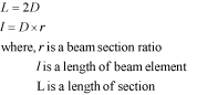
In the Advanced Option tab, the beam section ratio can be defined. This is used to calculate the length of the unit beam element.
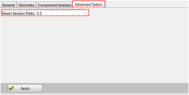
The length of the beam element can be calculated from beam section ratio as follows.
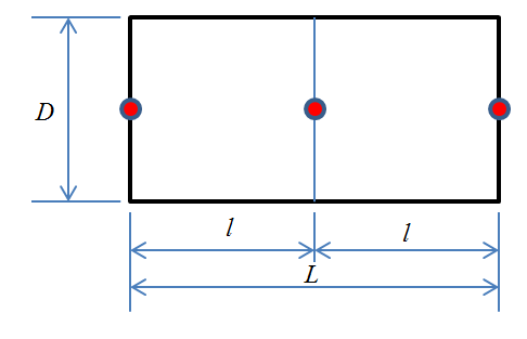
The beam elements are newly updated whenever gear or bearing is added to the Shaft Set as follows.
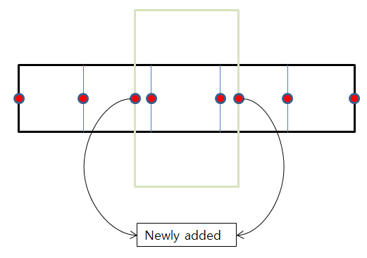
Also, the beam elements are newly updated whenever power load or point load is added to the Shaft Set as follows.
Geometry
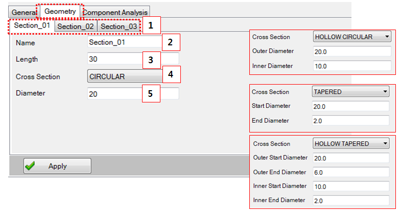
Figure 14.78: Parameters in the Simple Shaft Set designer Geometry tab
| Parameter | Description | Dimension |
| 1. Section | Use to select a section for modification | N/A |
| 2. Name | Use to set the section name. | N/A |
| 3. Length | Use to set the section length | Length |
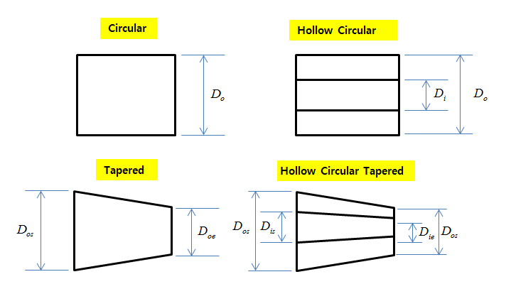
| 4. Cross Section | Use to select the section type. | N/A |
| 5. Diameter | Use to set the section diameter. This variable is depended on the type of cross section. | Length |
The dimension for each cross section can defined as follows.
Component Analysis
Refer to Component Analysis for an FE Shaft Set.