


There are three ways to create a Bushing as shown in the figure below. Connecting properties such as the acting and reacting bodies, and the locations and orientation on the bodies are defined in the Bushing creation dialog. When creating the force, two markers are created simultaneously to represent the force. When the Body-Body-Point option is used, the orientations of two markers are created from the identity matrices. When the Body-Body-Point-Direction option is used, the z-axes of the markers are defined as the specified direction. The other axes of the markers are determined by the right hand rule. Parameters in the dialog are defined in the table below.
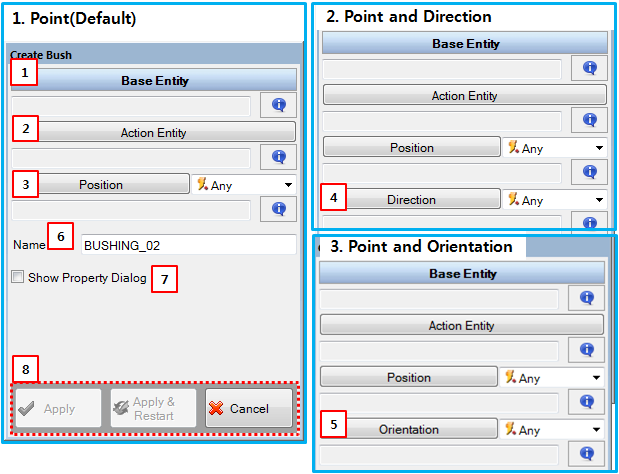
Figure 6.23: Description of parameters in the Bushing creation dialog
| Parameter | Description |
| 1. Base Entity | Use to select the reacting body using the General Picker. This defines the parent body of the base marker. |
| 2. Action Entity | Use to select the acting body using the General Picker. This defines the parent body of the action marker. |
| 3. Position | Use to set a location on the base and action bodies using the Point Picker. This defines the positions of the base and action markers. |
| 4. Direction | Use to set a direction on the base and action bodies using the Direction Picker. This defines the z-axes of the base and action markers. |
| 5. Orientation | Use to set the orientation on the base and action bodies using the Orientation Picker. This defines the orientations of the base and action markers. |
| 6. Name | Use to set the name of the Bushing. |
| 7. Show Property Dialog | Use to open the property dialog after finishing the creation operation. |
| 8. Control buttons | If all necessary parameters are set, these buttons are enabled. For more information about the control buttons, refer to Entity Creation. |