


Force parameters such as spring and damping coefficients and connecting properties such as the acting and reacting bodies, and the locations and the orientation on the bodies are defined in the Bushing property dialog as shown in the figure and table below.
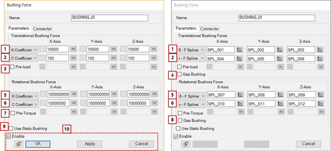
Figure 6.25: Description of parameters in the Bushing property dialog
| Parameter | Symbol | Description |
Dimension (Range) |
| Translational Bushing Force | |||
| 1. K Coefficient |

| Use to select a method to determine the spring force. When is selected, the translational spring coefficient matrix can be defined with constant values or a predefined Design Variable in x-y-z components. When is selected, the spring force curves can be defined with a predefined Splines using the spline picker in x-y-z components. For more information about these parameters, refer to Bushing Force. |
Force/Length (Real≥0.0) |
1.  -F Spline -F Spline |

|
Force (Spline) | |
| 2. C Coefficient |

| Use to select a method to determine the damping force. When is selected, the translational damping coefficient matrix can be defined with constant values or a predefined Design Variable in x-y-z components. When is selected, the damping force curves can be defined with a predefined Splines using the spline picker in x-y-z components. For more information about these parameters, refer to Bushing Force. |
Force*Time/Length (Real≥0.0) |
| 2. v-F Spline |

|
Force (Spline) | |
| 3. Pre-load |

| Use to set an actuating force with constant values or a predefined Design Variable. For more information about these parameters, refer to Bushing Force. |
Force (Real) |
| 4. Gap Bushing | N/A | This option is shown when is used instead of . Use to set the as zero if the value becomes zero during simulation. For example, in Figure 4.12: Non-linear Bushing Modeling for a Gap Contact, the becomes zero if the deformation is in the range between -gap and +gap. | N/A |
| Rotational Bushing Force | |||
| 5. K Coefficient |

| Use to select a method to determine the spring torque. When is selected, the rotational spring coefficient matrix can be defined with constant values or a predefined Design Variable in x-y-z components. When is selected, the spring torque curves can be defined with a predefined Splines using the spline picker in x-y-z components. For more information about these parameters, refer to Bushing Force. |
Force*Length/Radian (Real≥0.0) |
5.  -F Spline -F Spline |

|
Force*Length (Spline) | |
| 6. C Coefficient |

| Use to select a method to determine the damping torque. When is selected, the rotational damping coefficient matrix can be defined with constant values or a predefined Design Variable in x-y-z components. When is selected, the damping torque curves can be defined with predefined Splines using the spline picker in x-y-z components. For more information about these parameters, refer to Bushing Force. |
Force*Length*Time/Radian (Real≥0.0) |
| 6. v-F Spline |

|
Force*Length (Spline) | |
| 7. Pre-Torque |

| Use to set an actuating torque with constant values or a predefined Design Variable. For more information about this parameter, refer to Bushing Force. |
Force*Length (Real) |
| 8. Gap Bushing | N/A | This option is displayed when is used instead of . Use to set the to zero if the value becomes zero during simulation. For example, in Figure 4.12: Non-linear Bushing Modeling for a Gap Contact, the becomes zero if the deformation is in the range between -gap and +gap. | N/A |
|
9. Use Static Bushing |

| Use only to enable during static analysis. For neutral equilibrium problems such as contacts, free falling and a running vehicle, this option is very useful to find a static equilibrium position successfully. If the Bushing is connected between the ground and a sliding body with a stiffness coefficient in the sliding direction, the solver might be numerically stable during the static analysis. | N/A |
| 10. Control buttons | N/A | If all necessary parameters are set, these buttons are enabled. For more information about the control buttons, refer to Entity Properties Access and Modification. | N/A |
For more information about connectors, see Constraint Entity Connectors.