


Modeling of this problem involves the following steps:
The geometries are created in Design Modeler and attached to static analysis systems in the Workbench project schematic. Three static analysis systems are created, one for each case.
The coil has a radius of 0.3 mm, and the wire has a 0.05 mm radius with a 0.0125 mm initial gap between the filars.
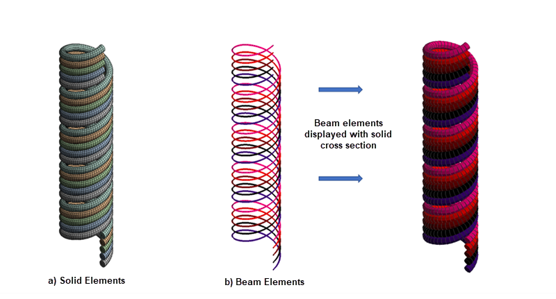
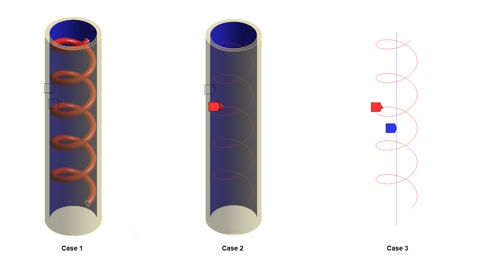
Case 1: Five layers of solid helical coils are created and meshed with solid elements (SOLID186). See a) in the figure below.
Case 2 and Case 3: A line model of helical coils is created and meshed with beam elements (BEAM189). See b) in the figure below.
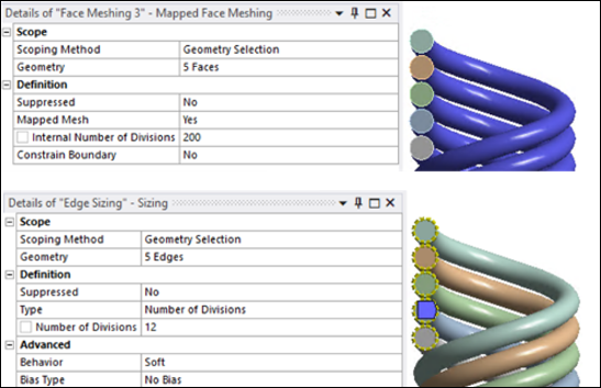
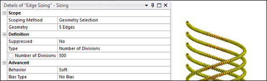
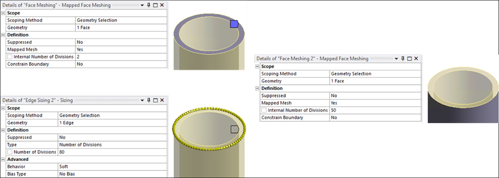
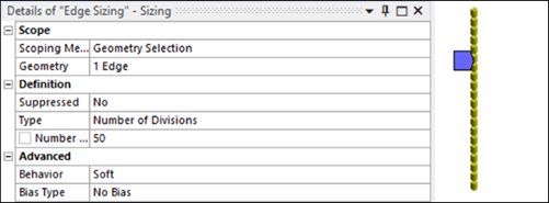
The corresponding mesh settings are shown below.
The tube is 3.45 mm long with an outer radius of 0.43 mm and an inner radius of 0.36 mm.
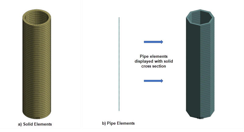
Case 1 and Case 2: A full three-dimensional model of the tube is created and meshed with solid elements (SOLID186). See a) in the figure below.
Case 3: A line model of the tube is created and meshed with PIPE289 elements. See b) in the figure below.
The corresponding mesh settings are shown below.
Two contact pairs are defined to simulate contact behavior in the model:
Because some contact settings in this example are not implemented in the Mechanical user interface, Mechanical APDL command snippets are used to define those settings. For information on adding command snippets, see Commands (APDL).
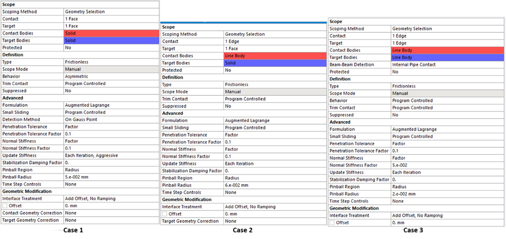
Contact between the coil and the inner tube surface is modeled differently for the three cases, as shown in Figure 51.8: Contact Pairs for Contact Between Coil and Tube:
Case 1: Surface-to-surface contact is used. The outer surface of the multi-filar coil is meshed with CONTA174 contact elements, and the inner surface of the tube is meshed with TARGE170 target elements.
Case 2: Line-to-surface contact is used. The multi-filar coil is meshed with CONTA175 contact elements, and the inner surface of the tube is meshed with TARGE170 target elements.
Case 3: Line-to-line (beam-to-beam) contact is used. The multi-filar coil is meshed with CONTA177 contact elements, and the tube is meshed with TARGE170 target elements.
The corresponding contact settings are shown in Figure 51.9: Contact Settings for Contact Between Coil and Tube.
The following contact settings (for CONTA177) are inserted as a command snippet, only for Case 3:
KEYOPT,cid,3,2     ! Include all contact scenarios
KEYOPT,cid,8,0
KEYOPT,cid,11,1    ! Include thickness effect
KEYOPT,cid,6,2     ! Aggressive stiffness variation.
KEYOPT,cid,14,2
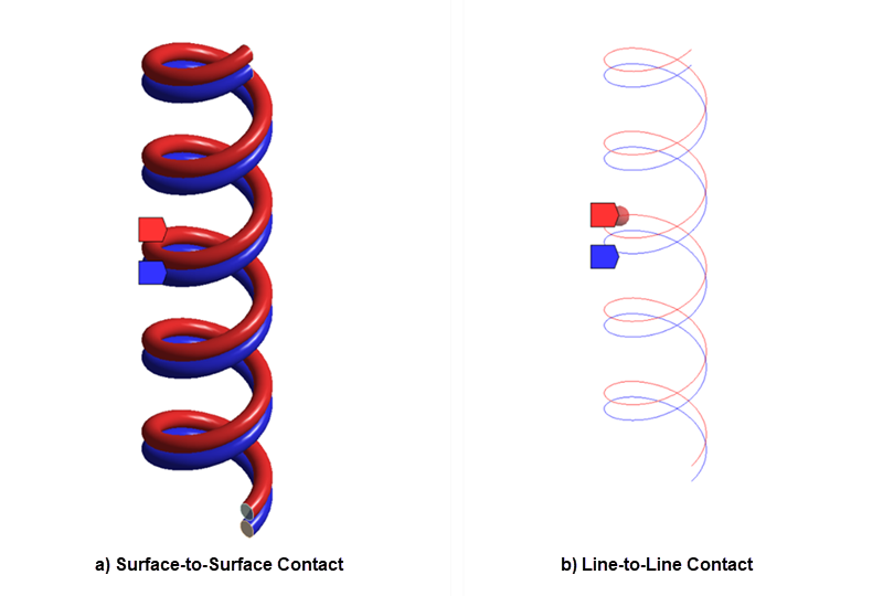
Self contact between the filar surfaces is modeled differently for the three cases:
Case 1: Self contact between the coil filars is modeled as surface-to-surface contact. The outer surface of the multi-filar coil is meshed with both CONTA174 contact elements and TARGE170 target elements. See a) in the figure below.
Case 2 and Case 3: Self contact between the coil filars is modeled as parallel line-to-line contact. The multi-filar coil is meshed with both CONTA177 contact elements and TARGE170 target elements. See b) in the figure below.
The corresponding contact settings are shown in Figure 51.11: Contact Settings for Self Contact Between Filars.
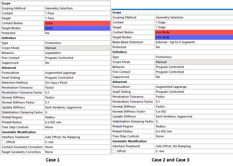
The following contact settings (for CONTA177) are inserted as a command snippet for Case 2 and Case 3:
et,cid,177
keyopt,cid,3,1     ! Define parallel beam-to-beam contact.
keyopt,cid,11,1
keyopt,cid,14,2    !Define multiple target segments interacting with each contact detection point.
keyopt,cid,6,2     !Aggressive stiffness variation.
keyopt,cid,8,0