A 2D Static Structural system has been created and set up to model this example problem using the bolt thread correction method (or simplified bolt thread modeling technique). The material properties (summarized in Material Properties) have been specified, and the 2D Behavior property for all bodies has been set to Axisymmetric. You can download the file named Bolt_Thread_2D_Simple.agdb to explore the setup hands-on using Ansys Workbench and the Mechanical Application (See Workbench Input Files and Project Files).
Multiple local coordinates have been created in the Static Structural system. They are used to define the locations of the bolt axis (the pretension elements location), the thread end point, and the path for evaluating Linearized Equivalent Stress. For information on creating coordinate systems, see Creating Coordinate Systems. The characteristics of the local coordinate systems are as follows:
Bolt_Axis:
Origin
Origin X = 0 mm and Origin Y = 260 mm
Principal Axis
Axis = X and Defined By = Global Y Axis
Bolt_Thread_End
Origin
Origin X = 0 mm and Origin Y = 162 mm
Path_Start
Origin
Origin X = 0 mm and Origin Y = 280 mm
Path_End
Origin
Origin X = 51.341 mm and Origin Y = 280 mm
This 2D assembly has the following contact regions:
Contact Region 1 – Between smooth edge (eqv threads) of bolt and base plate (Bolt thread To BasePlate thread).
Contact Region 2 – Between cover plate and base plate (CoverPlate To BasePlate)
Contact Region 3 – Between the bolt head and the cover plate (Bolt head To CoverPlate)
Each of these contacts have following settings (other than defaults) :
Definition
Type - Frictional
Frictional Coefficient - 0.15
Behavior - Asymmetric
Advanced
Formulation - Augmented Lagrange
Small Sliding - Off
Detection Method - Nodal-Projected Normal From Contact
Update Stiffness - Each Iteration
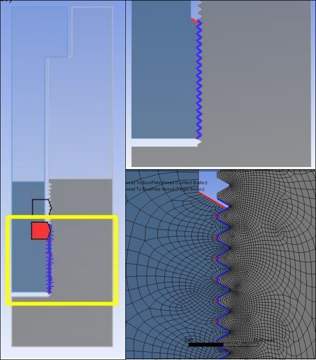
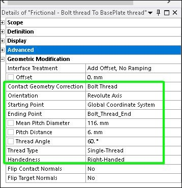
To simulate the bolt threads, the contact between the smooth edge (eqv threads) of the bolt and the base plate (Bolt thread To BasePlate thread), has additional Bolt ThreadContact Geometry Correction settings to simulate the bolt thread. The following figure shows the details of the additional settings for the Bolt Thread Correction.
The 2D model is meshed with 2D axisymmetric elements. Global Element Size is set to 6.5 mm. Local mesh Refinement (Refinement = 2) is applied on the smooth edge (eqv threads) of the bolt and the base plate to create a finer mesh for better thread simulation using the Bolt Thread Correction method. Mapped Face Meshing is also applied on all faces.
The analysis is non-linear with two load-steps. Auto Time Stepping is set On in each load-step to reduce the solution time. Large Deflection is set On to include large-deflection effects.
Pretension is the most important aspect of the simulation of the bolted structure. It transfers the load in the model while sustaining only a small part of the external load on the bolt. The preload on the bolt is caused by the tightening of the bolt to fasten the cover plate to the base plate. Pretension in the bolt is modeled by Bolt Pretension load, which cuts the bolt into two segments at the origin of the previously defined Bolt Pretension Coordinate System (y = 260 mm) and pulls each segment toward the other. Bolt Pretension creates pretension elements to simulate pretension in the bolt. For more information on using Bolt Pretension, see Bolt Pretension.
The bottom edge of the base plate is constrained in all directions using Fixed Support. A pressure load is applied to the upper edge of the cover plate after preloading the bolt.
The Bolt Pretension load applied on the bolt body is 2544690 N applied in first load step, which remains locked in during the second load-step (see details in the following figure).
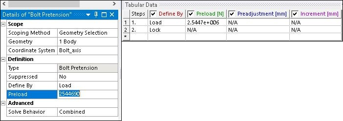
In the second load step, a pressure load of 50 MPa (which is less than the equivalent pretension load) is applied to the upper edge of the cover plate.
The MPC method is similar to the bolt thread correction method in all aspects except for how the thread contact region is modeled. Here, the Multi-Point Constraint (MPC) Contact Formulation with bonded contact type is used to simulate the thread contact region (between the smooth edge of the bolt and the base plate).
The settings for the thread contact region (other than defaults) are as follows:
Definition
Type - Bonded
Behavior - Asymmetric
Trim Contact - Off
Advanced
Formulation - MPC
Detection Method - Nodal-Normal To Target
You can download and import the Mechanical APDL common database .cdb mesh file to explore the most detailed modeling method, the true thread simulation method (See Workbench Input Files and Project Files). This method is similar to the bolt thread correction method except that the.cdb file is used instead of the CAD model. The more detailed geometry includes actual modeled threads for the true thread simulation method as seen in the following figure. As a result, the bolt thread correction used in the simpler modeling strategies is not needed here.