VM-WB-MECH-087
VM-WB-MECH-087
Campbell Diagrams and Critical Speeds Using Symmetric
Orthotropic Bearings
Overview
| Reference: |
Nelson, H.D., & McVaugh, J.M. (1976). The Dynamics of Rotor-Bearing Systems Using Finite Elements. Journal of Engineering for Industry, 98(4), 593-600. | |||
| Solver(s): | Ansys Mechanical | |||
| Analysis Type(s): | Modal Analysis | |||
| Element Type(s): |
|
Test Case
A rotor-bearing system is analyzed to determine the forward and backward whirl speeds. The distributed rotor is modeled as a configuration of six elements, with each element composed of subelements. See Table 1: Geometric Data of Rotor-Bearing Elements for a list of the geometric data of the individual elements. Two symmetric orthotropic bearings are located at positions four and six. A modal analysis is performed on the rotor-bearing system with multiple load steps to determine the whirl speeds and Campbell values for the system.
This problem is also presented in VM254
in the Mechanical APDL Verification Manual.
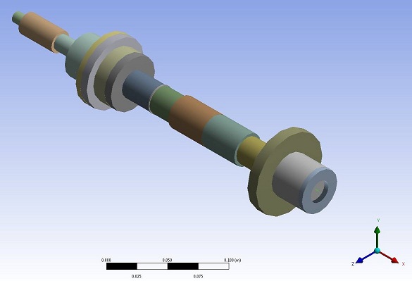
Table 1: Geometric Data of Rotor-Bearing Elements
| Element Number | Subelement number | Axial Distance to Subelement | Inner Diameter (cm) | Outer Diameter (cm) |
|---|---|---|---|---|
| 1 | 1 | 0.00 | 1.02 | |
| 2 | 1.27 | 2.04 | ||
| 2 | 1 | 5.08 | 1.52 | |
| 2 | 7.62 | 4.06 | ||
| 3 | 1 | 8.89 | 4.06 | |
| 2 | 10.16 | 6.60 | ||
| 3 | 10.67 | 1.52 | 6.60 | |
| 4 | 11.43 | 1.78 | 5.08 | |
| 5 | 12.70 | 5.08 | ||
| 6 | 13.46 | 2.54 | ||
| 4 | 1 | 16.51 | 2.54 | |
| 2 | 19.05 | 3.04 | ||
| 5 | 1 | 22.86 | 3.04 | |
| 2 | 26.67 | 2.54 | ||
| 6 | 1 | 28.70 | 2.54 | |
| 2 | 30.48 | 7.62 | ||
| 3 | 31.50 | 4.06 | ||
| 4 | 34.54 | 1.52 | 4.06 |
| Material Properties | Geometric Properties | Loading | |||||||||||||||
|---|---|---|---|---|---|---|---|---|---|---|---|---|---|---|---|---|---|
| Refer to Table 1: Geometric Data of Rotor-Bearing Elements |
|
Analysis Assumptions and Modeling Notes
A modal analysis is performed on the rotor-bearing system with QR Damp methods using pipe elements (PIPE288) to determine the whirl speeds and Campbell values.
A point mass is used to model the rigid disk (concentrated mass). Two symmetric orthotropic bearings are used to assemble the rotor system. No shear effect is included in the rotor-bearing system. The displacement and rotation along and around the X-axis is constrained so that the rotor-bearing system does not have any torsion or traction related displacements.
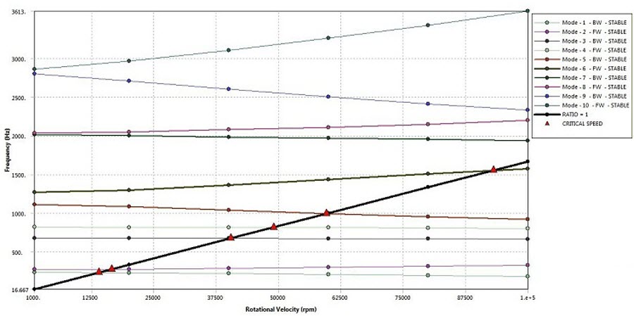
Backward and forward whirl speeds for slope = 1 @ 100000 RPM are determined from the modal analysis.
Results Comparison
| Target | Mechanical | Error (%) | |
|---|---|---|---|
|
Backward and forward whirl speeds for slope = 1 @ 100000 RPM RPM = Hz * 60 | |||
| PIPE288 | |||
| Mode 1 (BW) | 10747 | 10757.4 | 0.9677 |
| Mode 2 (FW) | 19665 | 19518 | -0.7475 |
| Mode 3 (BW) | 39077 | 39656.4 | 1.4827 |
| Mode 4 (FW) | 47549 | 48196.2 | 1.3611 |