


The commands issued by the Commands (APDL) objects affect the solution, however; they do not alter settings within Mechanical. This section describes how the following characteristics and requirements apply to Commands (APDL) object when used with the Mechanical APDL solver.
Text and Units
Command text cannot contain characters outside of the standard US ASCII character set due to the fact that this text will propagate into the Mechanical APDL application input files and must follow the rules set aside for the Mechanical APDL application commands and input files. Use of languages other than English for the command text may cause erratic behavior. The Mechanical APDL application commands should not be translated.
Make sure that you use consistent units of measure throughout your simulation. The application does not convert units of measure in the Commands (APDL) objects. Unit-dependent entries do not get converted if you make unit system changes in the analysis. Changes of this nature can lead to inaccurate results.
Commands (APDL) object input for magnetostatic analyses must be in MKS units (m, Kg, N, V, A).
Step Selection Mode
The Step Selection Mode property displays when you:
Have a Commands (APDL) object inserted under the environment and have Steps Controls defined.
or...
Are performing a Coupled Field Harmonic, Harmonic Acoustics, or a Harmonic Response analysis with the Multiple Steps property (Analysis Settings > Step Controls) set to .
or...
Are performing an MSUP Harmonic Response or Transient analysis (standalone or linked).
or...
Are performing a Random Vibration analysis.
- Stepped or Multiple Step Analyses
For stepped analyses, or multiple step Coupled Field Harmonic, Harmonic Acoustics, or a Harmonic Response analyses, this property enables you to specify which sequence steps are to process the Commands (APDL) object. The choices are: First, Last, All, and By Number. If you select the By Number option, the property Step Number displays. You use this property to specify the step during which your command(s) will execute.
- Solution Phase
For the following analysis types, the application executes the command based on the solution phase you specify.
Analysis Type Steps to Process Command MSUP Harmonic Response
MSUP Transient
- Random Vibration
For a Random Vibration analysis, this property provides the following options:
Random Vibration Solution: The application writes the Commands (APDL) object commands to the solver input file prior to the SOLVE command.
Participation Factors Calculation: The application writes the Commands (APDL) object commands to the solver input file prior to the PFACT command (participation factors calculation) for each load.
Note: If your analysis does not include any loads when you set the Step Selection Mode property to , the Command (APDL) object does not write any instructions to the solver input file.
Point Selection Mode
The Point Selection Mode property displays in the Details view of a Commands (APDL) object that is inserted under a Modal environment when the Campbell Diagram property is set to (Analysis Settings > Rotordynamics Controls). This property enables you to specify which Modal Points, as they correspond to the Campbell Diagram, are to process the Commands (APDL) object. Options include:
(default)
The By Number property enables you to choose specific Campbell Diagram solve points. When you select By Number, the Point Number also displays. Using this additional property, you specify individual and/or intermediate Campbell Diagram solve points to execute command(s).
The additional property Point Number displays when you select the option . You use this additional property to specify the Campbell Diagram solve point your command(s) will execute.
The Point Number value cannot exceed the Number of Points value specified in the Rotordynamics Controls. If you specify a Point Number that exceeds the value, the application defaults to the highest solve point available.
User Convenience Parameters
When a project is saved in workbench, the application’s project file management creates a directory/folder structure. The generated folders house a variety of files, such as input or result files. As a part of this structure, there is a folder created that is named user_files.
The Mechanical APDL solver input file, ds.dat, includes the following parameter (variable):
| _wb_userfiles_dir(1) |
The value of this parameter equals the path to the user_files directory.
You can use this parameter with the Commands (APDL) object and perform file operations in the Mechanical APDL language. For example, by specifying this parameter, you can copy result files to the user_files directory.
For a more specific example, accessing external user macros located in this directory might be done using the following Mechanical APDL command:
/INPUT, '%_wb_userfiles_dir(1)%file_aqld1001.dat'
For additional information on the Mechanical APDL Command language, see the Mechanical APDL Command Reference.
Output Parameters: Using Parameters Defined in Solution Command Objects
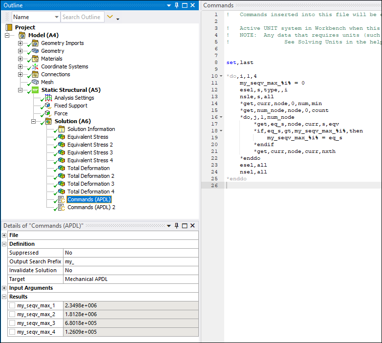
When you insert a Commands (APDL) object under the Solution object, the Details pane includes the property: Output Search Prefix. You use this property to specify a desired prefix to create searchable variables/parameters in result files.
When defining a parameter that includes a Output Search Prefix, you must:
Use the equals (=) symbol to specify your parameter (
my_parameter =
          1
). Or, you can...Specify your parameter as an input argument for a *set or *get command.
Note: When you are entering a large number of output parameters, you could experience lag in the Command pane worksheet. To counter this condition, Ansys recommends that you create a complete command entry in text file format and then either import the file or copy and paste the complete entry into the worksheet.
Range Entries and Do Loops
The above entries can be created within Do...Loop statements. And, within the Do Loop, you can make use of variables inside percent (%) symbols to easily define a range of parameter values. When creating the output parameters containing variables inside of percent (%) symbols, the following rules apply:
The variable inside of the symbols must be set using:
The equals sign (variable = integer value).
*SET, variable, integer value.
The iterator of a supported Do Loop (nested do loops are also supported).
When creating the output parameter, the (%) symbols and the variables inside them are replaced by the value the variable has been set to using equal (=) symbol or *SET command, or if the variable is the iterator of a Do Loop, a range of parameters are created according to the limits of the Do Loop.
Do loops with positive integers as upper and lower bounds and integer increments are supported if:
The loop’s upper bound greater than/equal to the loop’s lowed bound and the loop’s increment > 0.
Or...
The loop’s upper bound less than/equal to the loop’s lowed bound and the loop’s increment < 0.
The Do Loop’s upper and lower bounds can be parameters which are set via (variable = integer value), or (*SET, variable, integer value).
Results
When you create an entry in the Command pane (worksheet) using a Output Search Prefix and a parameter, the application automatically:
Displays your new prefix/parameter in the Results category of the Details pane.
Searches the result file for matches (after the solution process) and then displays the results values. An example is illustrated below.
This example uses the default Output Search Prefix property entry, "my_". If you change the prefix at any time, the application automatically rescans the result file for matches.
Note:
If you have parameterized an output parameter in the Commands APDL object, you cannot edit the command text. You need to remove the parameters to edit the text
You can use generated parameters in Design Exploration.
Mechanical APDL Application Plots in Mechanical
You can view Mechanical APDL application plots in Mechanical that result from using Commands APDL objects. The Mechanical APDL application plots are returned from Mechanical APDL to display in the Worksheet. This feature is useful if you want to review result plots that are available in the Mechanical APDL application but not in Workbench, such as unaveraged stress results or contact results only on a particular region.
To View the Mechanical APDL Application Plots in Mechanical:
Create one or more Commands APDL objects.
Direct plot(s) to PNG format.
Request plots in the Commands APDL objects.
Make sure that there is at least one Commands APDL object under Solution in the tree.
Solve. Requested plots for all Commands APDL objects are displayed as objects under the first unsuppressed Commands APDL object that appears below Solution.
Note: The Mechanical APDL application PowerGraphics mode for displaying results is not compatible with Commands APDL objects. No results will be produced in this mode. If your command list includes the PowerGraphics mode (/GRAPH,POWER), you must switch to the Full mode by including /GRAPH,FULL at the end of the list.
Presented below is an example of a Commands APDL object used to create two plots, one for unaveraged stress, and one for element error.
!   Commands inserted into this file will be executed immediately after the Ansys /POST1 command.
!   If a SET command is issued, results from that load step will be used as the basis of all
!   result objects appearing in the Solution folder.

set,last      ! read the last data set
/show,png     ! output to png format

/gfile,650    ! adjust size of file

/edge,1,1     ! turn on element outlines
/view,,1,1,1  ! adjust view angle

ples,s,eqv    ! plot unaverage seqv
ples,serr     ! plot element error
The Mechanical APDL application plots are shown below.
Unaveraged Stress Result:
Element Error Result:
Commands APDL Objects and Materials
When using Commands APDL objects:
Do not change the material IDs for elements. This will cause the results retrieval form the Mechanical APDL application to Workbench to malfunction.
Instead of adding one large Commands APDL object to change all of the materials, add individual Commands APDL objects under each part. That way you will be able to reference the
matidin the Commands APDL object for the material ID of the elements that make up the part. You will also only need to enter the adjusted coefficient of thermal expansion and not the other materials.Use the Worksheet view of the Geometry object to determine which materials are assigned to specific parts.
Click the right mouse button on a selected item in the Worksheet view, then choose to add Commands APDL objects.
Copy and paste Commands APDL objects from one part to another that have the same material assignment.
Note: When specifying the same material to multiple bodies using Material Assignment object, the application
can no longer identify the bodies using the material identifier
(matid) in the solver input file. In this case, you can use the
typeids list to identify a body. The identifier
typeids is a one-dimension array parameter that you can use to access
the type numbers for a body. You can access type numbers using a subscript (enclosed in
parentheses) to identify the required item of the array. For example, to access the first
type number for the body use typeids(1).
Mechanical and Mechanical APDL Applications Conflicts
In order to utilize the Command object feature and execute Mechanical APDL application commands in Mechanical, you must have a thorough understanding the use of Mechanical APDL Commands. Moreover, you need to understand that there are times when Mechanical APDL commands may conflict with the internal settings in Mechanical and as a result adversely affect your solution values.
The following are some common conflicts that could arise:
If you define only linear elastic properties in Engineering Data, it is possible to use the Mechanical APDL application commands in a Commands APDL object to override the material properties defined in Engineering Data or even change the linear elastic material model to a nonlinear material model, such as adding a bilinear kinematic hardening (BKIN) model. In this case, the solution uses the BKIN model defined in the Commands APDL object. However, since Mechanical is unaware of the nonlinear material specified by the Commands APDL object, nonlinear solution quantities such as plastic strain will not be available for postprocessing.
The Mechanical APDL application applies nodal boundary conditions in the nodal coordinate system. For consistency, Mechanical must sometimes internally rotate nodes. As a result, any node-based boundary conditions defined in a Commands APDL object will be applied in the rotated nodal coordinate system.
Commands support the definition of Mechanical APDL arguments via the settings of the properties ARG1 through ARG9. Once a value for one of these arguments is set, it will be retained for the remainder of the Mechanical APDL solve run unless explicitly set to zero in the Commands text.
Mechanical assumes certain behaviors with respect to Mechanical APDL solution file names and locations. Therefore, unexpected behavior could occur if Mechanical APDL commands such as /RENAME, /FILNAME, and /ASSIGN are used in a Commands APDL object which alters the solution files.
Using Mechanical APDL Commands in the Mechanical application requires a working knowledge and experience with Mechanical APDL Commands and therefore, it is your responsibility to make sure that any command that you are issuing does not conflict with any existing Mechanical application requirement.
Important: It is important to note that not all of the Mechanical APDL Commands are available for use in Mechanical. For example, the command RAPPND, that physically alters the result file is not currently supported. Furthermore, using commands that change the numbering of nodes or the numbering of elements or change how nodes are arranged on elements will most likely cause post processing errors.