


The Solid option of the Construction Geometry feature enables you to create and add a solid part to the model you have imported into Mechanical.
To define a Solid Construction Geometry:
Highlight the Model object, open the drop-down menu on the Model Context Tab, and select .
As needed, specify a coordinate system. The default is the .
Specify the dimensions of the solid part using the X1 through Z2 properties. These properties define the start point and the end point for each dimension. The application displays a frame of your geometry as you enter values.
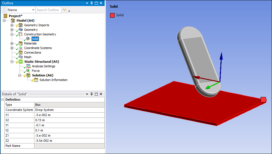
Important:The difference between the X, Y, and Z values must be greater than zero and within a tolerance of 1e-10. All comparisons are performed in the associated CAD units.
Automatic contact detection is not performed when a solid part is generated. In order for the solid part to be included in automatic contact generation, you need to either select option via the Connections folder or update the geometry from the CAD source by selecting the option via the Geometry folder.
Making a vertex or node selection on your model displays the Location of the vertex/node in the Status Bar. This information can be helpful when constructing your solid part.
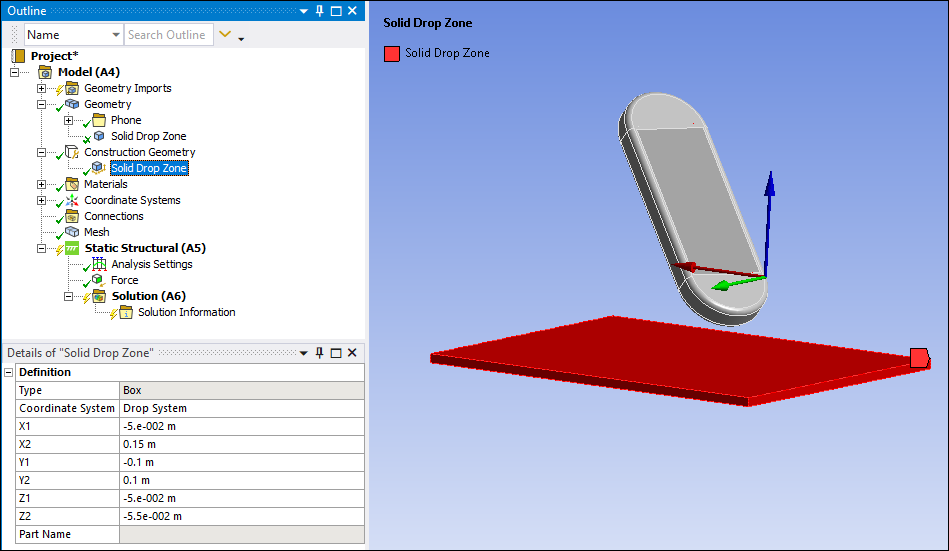
Right-click the object and select . Once created, a new Part is placed in the Geometry folder. This part behaves as and may be used like any part of the model.
Note: Review the following requirements:
You must update the Geometry object ( option) in order to transfer changes made on the Solid object to the Part object.
In order to delete a Solid object, you must first right-click the object and select . This action removes the part from the Geometry folder. You can then delete the Solid object as needed.
Selective Update is not supported for solids created in Mechanical.