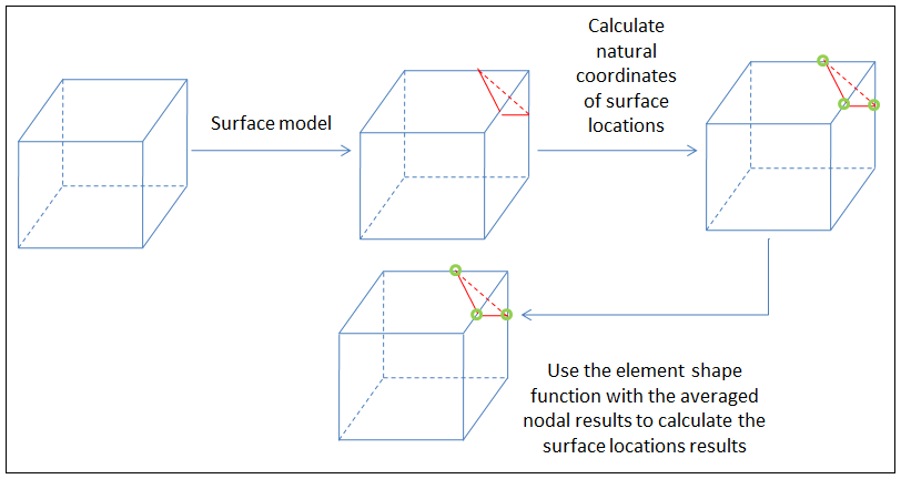
If you have already defined a surface, you can view the surface results by first adding a standard result or user defined result, and in the Details view of the result object, setting Scoping Method to Surface, then choosing the name of the particular surface that you defined.
Note: Surface results are not supported for models using periodic or cyclic symmetry.
The Details view for a surface result contains an additional item called Average, which can be parametrized.
For example, average stress over the surface is given by:
{ ∫ Stress(X, Y, Z) dAREA} / {TOTAL_AREA}
For some results, the Details view will also contain a Total quantity, such as Total Force, which also can be parametrized.
The Total quantities are presented in the following table. Currently, if you desire a Total quantity for Heat Flux, Magnetic Flux Density, Current Density, or Electric Flux Density, you must choose a vector user defined result. Total Force (as integrated from principal stress vectors) is available to both standard and user defined results.
| Identifier | Result | Surface Integral |
| TFVECTORS | Heat Flux | Heat Rate |
| BVECTORS | Magnetic Flux Density | Magnetic Flux |
| DVECTORS | Electric Flux Density | Charge |
| JTVECTORS, JCVECTORS | Current Density | Current |
| SVECTORS (also see Vector Principals) | Stress Tensor | Force |
Interpolation of Data on a Surface
For a given surface (such as the intersection of a cutting plane and a finite element
mesh), Mechanical examines each element in the set of scoped bodies to determine if any element
edge was intersected by the surface. A surface may intersect multiple edges of a finite
element, so Mechanical maintains a list of all (x,y,z) points and all
element IDs from the edge intersections. This set of intersection points is, in essence, a set
of interpolation points.

For example, you request a normal x-axis stress result on the surface (that is,
SX). For a given interpolation point (x,y,z)
lying on an edge of an element, Mechanical finds the natural (or normalized) coordinates of the
point within the element. Mechanical then interpolates the corner values of
SX, using the natural coordinates and shape functions, to find a value
for SX at (x,y,z).
See the Interpolation section for additional information.
Force and Moment Reactions
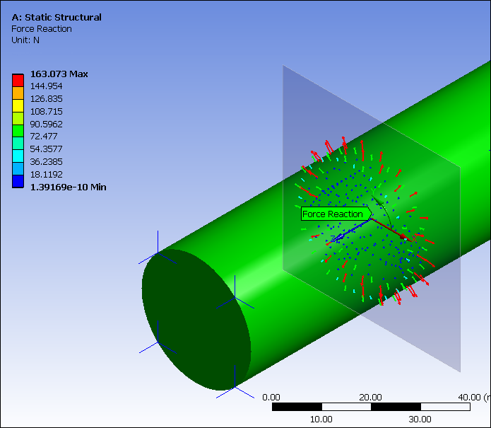
For a pre-defined surface, a surface probe enables you to study reactions on cutting planes. You can extract generated member forces and reactions through a model by using a reaction probe scoped to a surface.
For this probe type, you must explicitly select the bodies to be sliced. You cannot apply this to "all bodies." You then specify for the Extraction detail whether you want to study nodes in front or behind the plane. The probe will only operate on elements cut by the plane (and only nodes on those elements which are on the selected side of the plane). Note that the surface probe will display nodal forces for all nodes that are involved in the reaction calculation.

Surface Displays and Fracture
Mechanical analyzes for duplicates the sets of (x,y,z) for the facets in a surface construction object and compresses it by discarding all duplicate (x,y,z) sets. Mechanical employs compression to reduce the size of the data cache and to improve performance.
For each remaining (x,y,z) in the surface, Mechanical derives via interpolation the results (like displacements and stresses) from precisely one element. That is, even if an (x,y,z) resides in many elements, Mechanical only fetches the displacements from one element.
Hence, interpolated displacements at the (x,y,z) may currently fail to demonstrate the proper deformation of a crack.


