


If you encounter fracture meshing failures, first refer to the Fracture Meshing section of the Help for detailed information about the requirements, characteristics, and limitations of fracture meshing. Otherwise, review the troubleshooting options described below.
Handling Cracks Close to Face Boundaries
When a crack is defined close to a common edge shared by two faces and that common edge has been defeatured so that the mesh topology does not conform well to the topology of the geometry, the fracture mesh generation might fail. This is because there may be elements which span across the common edge.
To correct this problem, be careful to ensure the edge of the geometry is captured in the mesh.
See Topology Checking for more information.
Handling Shallow Crack Failures
A crack failure can be caused if the Major/Minor Radius ratio is greater than 3:1 and there are a high number of crack divisions. To correct this problem, reduce the Crack Front Divisions when defining the crack. The recommended range is from 9 to 21 divisions.
A Large Contour Radius relative to the size of the crack might also cause a Fracture Mesh generation failure. In this case, reduce the contour radius.
For more information, see the Defining a Semi-Elliptical Crack topic in the Fracture Meshing section of the Help.
Handling Crack Errors for Multiple Cracks
If you define multiple cracks it might take a long time before the mesh fails. This is because multiple cracks are generated sequentially. When more than one crack is defined, a crack with an undesired parameter definition can only be detected after the cracks in front of it are generated.
To correct this problem, either increase the buffer zones so that they overlap each other or reduce them so that they are farther apart from each other.
Handling Buffer Zone Issues
When two Buffer Zones are very close, but not close enough to be combined as one zone during crack mesh generation, crack mesh generation might fail. To prevent this, re-size the buffer zones such that they either overlap or are farther apart from each other.
If long and skinny tetrahedral elements are generated inside the Buffer Zone, increase the size of the zone using the scale factors. Also, refine the Base Mesh relative to the crack size.
Handling Base Mesh Issues
If the tetrahedra near the crack template boundary are long and skinny, the cause might be that the base mesh is coarse compared to the crack size. To fix the tetrahedra, either increase the buffer zone or refine the base mesh around the cracks.
If the crack mesh generation fails, it might be because the base mesh is either very coarse or very fine compared to the crack definition. To correct this problem, regenerate the base mesh with a mesh size relative to the crack definition. You should also scale the buffer zone to the crack definition.
If the crack mesh generation fails due to base mesh size, regenerate the base mesh with a size relative to the crack size.
Handling Fracture Affected Zone Definition Failures
If an error occurs when the crack template is inserted, it can be caused by one or more of the following:
The Fracture Affected Zone Height is big compared to the contour radius. If the height is too large, layers outside of the contour will not look good.
The Contour Radius is too big compared to the crack definition
There are a large number of mesh contours
There are a large number of Crack Front definitions
To correct these problems, you can:
Reduce the Fracture Affected Zone Height manually or use the Program-Controlled option.
Reduce the contour radius. The radius should be small enough to allow room for one layer of an element outside the contour.
Reduce the number of mesh contours.
Reduce the Crack Front divisions. Make sure, however, that there are at least nine Crack Front divisions.
Handling X-Axis Rotation and Alignment
If the X-Axis of the coordinate system which is used to define the crack is not aligned along normal of the surface on which the crack is inserted, the mesher issues a warning message and rotates the X-Axis to be consistent with the surface normal.
Handling Projection to the Surface
If the origin point of the coordinate system is not on the surface of the scoped body, the crack mesher automatically inserts a crack on a face of the scoped body that is nearest to the origin location. Note that the chosen model face may be different than the intended model face. The mesher picks the face nearest to the location of the origin.
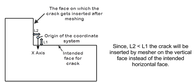
To ensure the mesher chooses the intended model face, use the Create Coordinate System Aligned with Hit Point Normal option:
Click the Hit Point Coordinate button on the Graphics Toolbar.
Select the point on the face where you want the origin to be located.
Right-click the point and choose Coordinate System Aligned with Hit Point Normal.
Improving Mesh Quality
Note that aggressive shape checking is available for Base Mesh generation, but is not available for Fracture meshing.
High aspect ratio elements might be generated:
Around the crack tip if a smaller number of crack front divisions are used.
Near the buffer zone boundary if a small crack is defined in a coarse base mesh.
To improve mesh quality:
Increase the Crack Front divisions within a range of 9-21 divisions.
Increase the Buffer Zone or regenerate the Base Mesh with respect to the crack size by using Local Sizing Control with Sphere of Influence.
Handling Cracks on High Curvature Surfaces
When you define a crack on a highly curved surface, such as the one shown below, the generation of the crack may fail.
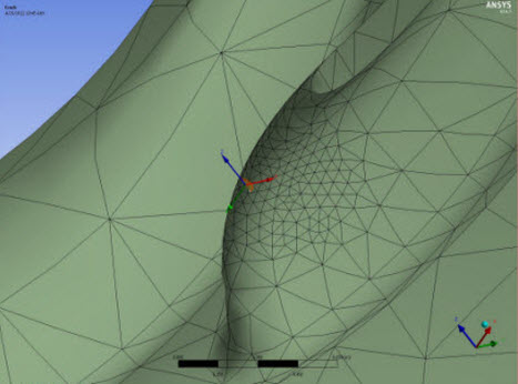
To correct this, use the information from feedback messages to redefine the crack definition and/or modify the mesh region on which the crack is inserted.