


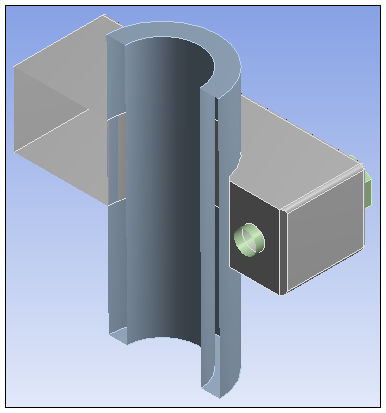
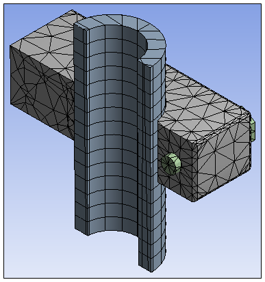
The Section Plane acts differently depending if you are viewing a result, mesh, or geometry. When viewing a result or a mesh, the cut is performed by a software algorithm. When viewing geometry, the cut is performed using a hardware clipping method. This hardware clipping cuts away the model in a subtractive method. The software algorithm cuts away the model but always starts with the whole model. Examples of these methods are illustrated below.
Note: The software algorithm always caps the surfaces created by the section plane as opposed to the hardware clipping method that may or may not cap the surface depending on the display options you have selected. See the Creating Section Planes section for the capping display options. When capping, the software algorithm creates a visible surface at the intersection of the object and the section plane.
|
Geometry Display |
Mesh Display |
|
|
|
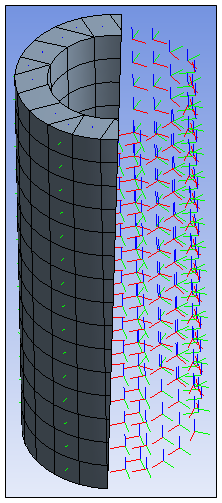
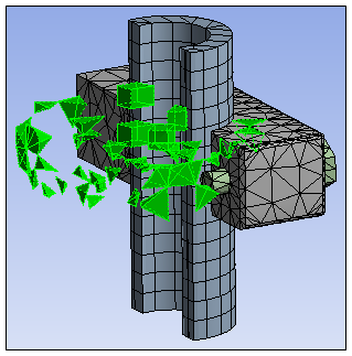
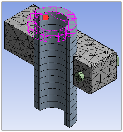
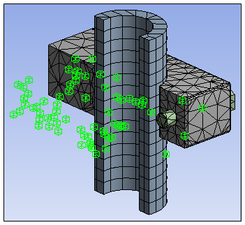
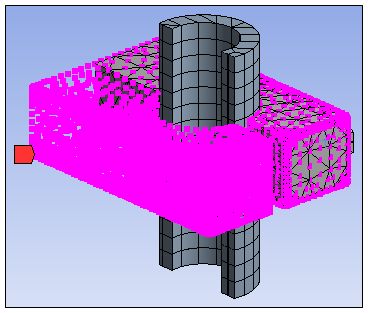
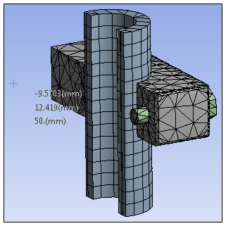
In addition, and as illustrated in the examples below, Section Planes do not cut the orientation or element displays if you employ:
Element Orientation feature
Element-based, element face-based, or node-based selections
Named Sections scoped to elements, element faces, or nodes
Hit Point selections
|
Element Orientation Display |
Element Selections |
|
|
|
|
Element-Based Named Selection Display |
Node Selections |
|
|
|
|
Node-Based Named Selection Display |
Hit Point Display |
|
|
|