The Node Move feature enables you to select and then manually move a specific node on the mesh to improve the local mesh quality.
Requirements
This feature has the following topological requirements:
Node movement is restricted to the target part. That is, nodes cannot be moved outside of the part.
Face/Edge nodes can be moved along the corresponding face/edge only.
The application locks corner nodes to the underlying vertex.
Moving a node on a solved analysis causes the solution data to become obsolete. However, the state does not become obsolete for other objects that depend on the mesh (for example, imported loading conditions, Element Orientations). If your node movement changes affect other objects, you will need to manually clear and refresh these objects to apply the new changes.
The Node Move feature is disabled if you are working with Section Planes.
Application
The Node Move object is a child object of Mesh Edit. It is inserted into the tree by selecting the Node Move button on the Mesh Edit toolbar or by selecting the Mesh Edit object, right-clicking, and selecting >.
To use this feature, you need to generate the mesh on your model. This can be done before or after you have inserted the object into the tree. Once generated, the node selection options are assigned automatically. The Select Type is set to Select Mesh and Vertex is the required picking tool. Moving the cursor across the mesh of your model displays the available mesh nodes. You may then select and move nodes.
In addition, once the object is placed in the tree, the Node Move toolbar displays.

Node Move toolbar options include the following:
- Undo Last
Cancels the last node movement performed on the mesh. Operations that change the original mesh may make this option unavailable.
- Undo All
Cancels all of the node movements that you have made to the mesh. Operations that change the original mesh may make this option unavailable.
- Probe, Max, and Min
These are annotation options. Selecting the Max and/or Min buttons displays the maximum and minimum values for mesh criteria (Element Quality, Jacobian Ratio, etc.) that you have selected. The Probe feature is also criteria-based. You place a Probe on a point on the model to display an annotation on that point. Probe annotations show the mesh criterion-based value at the location of the cursor. When created, probe annotations do not trigger the database to be marked for the file needing to be saved (that is, you will not be prompted to save). Be sure to issue a save if you wish to retain these newly created probe annotations in the database. These options are not visible if the Mesh object Display Style property is set to the default setting, .
- Edges Options
This drop-down menu provides options to change the display of your model, including:
: displays a basic picture of the body.
: displays element outlines.
These options are the same options that are available on the Meshing Context Toolbar.
Free Mode
You can depress the F4 key while you are moving a node to remove certain movement restrictions. This mode enables you to move an edge, vertex, or face node anywhere on a given face.
Direct Node Movement
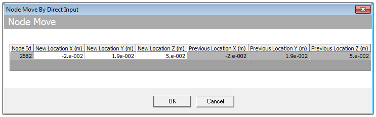
You can also move a node by manually selecting the desired node, right-clicking, and then selecting the option .
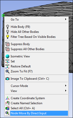
This option displays an entry window where you can manually change the X, Y, Z location of the node.
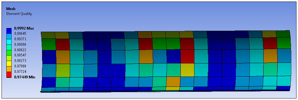
Element Quality Display
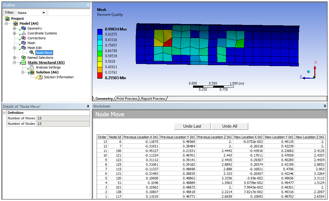
To enhance the presentation of your selections and movements, make sure that you set the Display Style property of the Mesh to . An example of this setting is provided below. The exact display is provided on the Node Move object (and the legend title is also Mesh).
Worksheet
The Worksheet works in combination with the Node Move feature. The Worksheet records all of the node movements performed. In addition, and as illustrated below, the Worksheet provides information about the selection order of node movements, node numbers, coordinate-based location information (previous and new), as well as the options to undo the last movement or all of the movements that were made.
Note: If you update your mesh (Mesh object>), the application maintains your movements in the Worksheet until the mesh is cleared (zero nodes) using the RMB option or you refresh data from the CAD source.
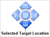
The illustration above also shows the Worksheet docked in the lower portion of the screen so that you can easily see all of your node movement information while also being able to see the model. Docking is possible with the docking tool shown here. This tool displays when you drag a window's title bar. Hovering the window over one of the blue arrows highlights the arrow. Releasing the mouse button docks the window in that screen location. It may also be useful to display the node numbers on your model using the display option Node Number available through Annotation Preferences.
Note: Node move operations are not persistent. The Worksheet view gives a history of what has been done based on the current Node IDs, but new Node IDs are created when the model is re-meshed. Therefore, the history recorded in the Worksheet is rendered out-of-date after re-meshing. For this reason, Node Move operations should be used sparingly, and only to fix small issues.
See the Windows Management Help section for additional information.
Example
The following is an animated example of the use of the feature in tandem with the display. View online if you are reading the PDF version of the help. Interface names and other components shown in the demos may differ from those in the released product.