


The DesignModeler application distinguishes between plane/sketch or feature dimensions and design parameters. A model easily contains hundreds of dimensions. It is not useful to consider all of them for parametric studies. Thus, the DesignModeler application allows you to "promote" a selected set of these to Design Parameters. The tool includes two tabbed windows:
To display the Parameters windows, click the feature in the toolbar or choose the menu item from the Tools Menu. You can edit the text that appears in most of the cells of each window. Both tabbed windows display five columns: State, Name, or Target; Value or Expression; Type; and Comment. The first, unlabeled, displays the “state” of a particular line. It can have one of five states:
Okay:
 , if it has no errors and has not been
modified
, if it has no errors and has not been
modifiedComment:
 , if it does not have a
name or a name and an expression
, if it does not have a
name or a name and an expressionModified:
 if it has been
modified — Needs the “Check” button
if it has been
modified — Needs the “Check” buttonSuppressed:
 , it will not be
used unless unsuppressed
, it will not be
used unless unsuppressedError:
 , invalid for some reason
The Type column can contain any of these values, which help to categorize the parameter:
Undefined
Length
Angle
Dimensionless
Area
Moment of Inertia
Warping Factor
Volume
Note:
The Volume parameter type is available only by selecting it from the Type drop-down menu. No promotable parameters generate the Volume type.
In releases of DesignModeler prior to Release 15.0, all parameters were treated as Dimensionless.
You can also add a comment to the last column for any parameter or assignment row, which will appear in green text.
On each tabbed window are two buttons:
Distinguishable characteristics include:
Design Parameters Tab
The text in the Design Parameters window lists the specified parameters and their values, line-by-line. Values can be specified using scientific notation (e or E) if needed.
The parameters listed here are also promoted to the DesignModeler Project Schematic Operations page, with the appropriate units for Length and Angle parameters. If you change values on the Project page, then you should use “Refresh Input” in DesignModeler’s File menu, or a Refresh or Update command from the Project page to send that change down to DesignModeler.
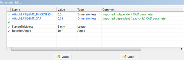
Some parameter information cannot be changed. It will appear in blue text in the window to indicate it is not editable. For example:
Names of design parameters that come from imported CAD models
Physical properties of cross sections that you have promoted
Dependent (read-only) CAD parameters that you have promoted
These will appear in the Project Schematic as output parameters, and their definitions in the Design Parameters window will appear in blue text.
Note that these Design Parameters may be filtered according to the Parameter Key that isspecified in other applications.
See Sending Parameters to the Mechanical Application for information specific to the Project Schematic.
Parameter/Dimension Assignments Tab
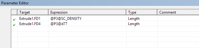
The text in the Parameter/Dimension Assignments window lists a sequence of "left-hand-side = right-hand-side" assignments, displayed in the Target and Expression columns, which are used to drive the model dimensions by the given Design Parameters.
The Target is a reference to one of the plane/sketch or feature dimensions, or, optionally, a reference to an auxiliary "variable".
The Expression is an arbitrary expression in +, -, e+, e-,*, and /, including parentheses, referencing Design Parameters (here, the syntax uses the "@" prefix) and feature dimensions, but also numeric constants or references to auxiliary variables and parametric functions. The DesignModeler application will evaluate the right-hand side of each expression, and use the resulting value to drive the dimension referenced in the Target.
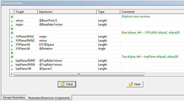
Plane/sketch dimensions are referenced by the plane's name, followed by a period ("."), followed by the dimensions name. The syntax for feature dimensions is as follows: feature name, followed by a period ("."), followed by 'FD1,' 'FD2,' ... ("Feature Dimension 1," "Feature Dimension 2," ...) according to the Details View of the corresponding dimensions property of the feature in question.
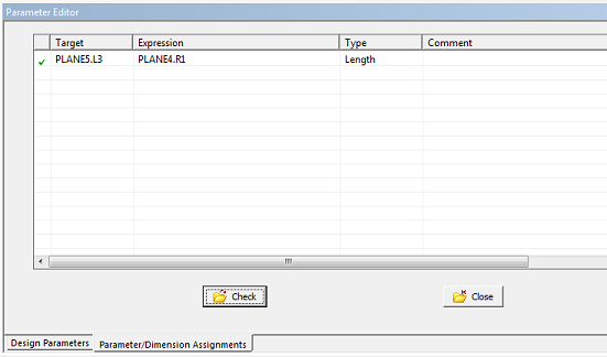
These expressions can also be used to make a dimension in one plane or feature drive the dimension of another plane or feature.
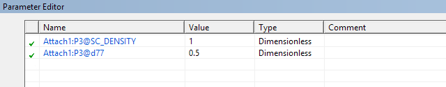
Note: Occasionally parameters coming from CAD systems (may) contain colon characters in their name. Although these parameters can be promoted to the DesignModeler Parameter Manager, they cannot be used in the Parameter/Dimension Assignments Tab.
When assigning design parameters originating from CAD systems, exclude the feature name from the assignment, as shown below.
Check Button
The Check button triggers an execution of the Parameter/Dimension Assignments without updating the model. This can serve as a "syntax check" in case you are using nontrivial assignments. In some cases you may need to click Check twice because of multiple nested dependencies. You may also need to Generate the model more than once due to interactions between Sketch Dimensions and the model. This is especially true when planes are created from faces and dimensions or constraints depend on face boundaries. If errors are detected during a Check operation, Design Parameter and/or Parameter/Dimension Assignment rows will be marked with the error status; an error message can be read by right clicking the top of the treeview.
Close Button
The Close button closes the tab, and returns to the model-only view.
Distinction between Design Parameters values and Parameter/Dimension Assignment values
When you promote a feature property or dimension to be a parameter, it uses the name you give it at that time and the current value of that feature property or dimension for the Design Parameters entry. This is the name and value that are sent to the Project page. When you create this Design Parameters entry, a corresponding entry is automatically created in the Parameter/Dimension Assignments Tab. If you change the value in the Design Parameters tab, or on the Project page, it will use that value in any assignments on the Parameter/Dimension Assignments Tab, including any that change the actual feature/dimension value. However, if you were to change the assignment table so that a feature/dimension is assigned something other than a direct assignment of the entry in the Design Parameters Tab, that assignment will override the value in the feature/dimension. It will not affect the value in the Design Parameters entry or the value on the Project page. The entries in the Design Parameters Tab (and Project page), can be considered initial values for that variable. You can use that variable to assign back to the feature/dimension or change the assignment to something else, but that will not affect the “initial value” of that variable. In those cases, what appears in the Design Parameters entry may not be the same as that feature/dimension value.
Other Parameters topics: