The Body Transformation features allow you to reposition or transform bodies. Any type of body can be used with body operations, regardless of whether it is active or frozen. However, point feature points (PF points), attached to the faces or edges of the selected bodies, are not affected by the body operation.
The Body Transformation features available are:
Move
Translate
Rotate
Mirror
Scale
Move
The Details View is used to set the Move type:
Use to keep the original body by setting the Preserve Bodies option to Yes. If the original body is not required, set the Preserve Bodies option to No.
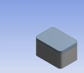
Example 76: Aligning Imported/Attached Bodies By Plane
Select bodies and two planes: a source plane and a destination plane. Upon clicking Generate, Ansys DesignModeler will transform the selected bodies from the source plane to the destination plane. This is especially useful for aligning imported or attached bodies. Typically, these planes will be planes created from the faces of the bodies at hand.
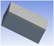
Two imported bodies that do not align properly:
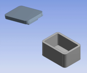
The cap is moved using Body Operation's Move option:
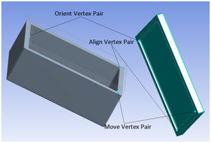
Example 77: Aligning Imported/Attached Bodies By Points
Select bodies and pairs of points for Move, Align and Orient. Points can be Vertices, PF Points, or 2D Sketch Points. Upon clicking Generate, Ansys DesignModeler will transform selected bodies with Move points defining translation and Align, Orient defining rotation respectively. Typically, these points belong to source and destination bodies. You can choose not to specify Orient and Align. However, input for Align property is necessary if Orient is specified.
 |  |
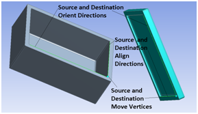
Example 78: Aligning Imported/Attached Bodies By Direction
Select bodies, pair points for Source and Destination Move and directions for Source and Destination Align and Source and Destination Orient. Points can be Vertices, PF Points, or 2D Sketch Points. Upon clicking Generate, Ansys DesignModeler will transform selected bodies with Move points defining translation and Align, Orient defining rotation respectively. Typically, these points belong to source and destination bodies. You can choose not to specify Orient and Align. However, Align is necessary if Orient is specified.
 |  |
Translate
Use to select bodies to translate in a specified direction. You can specify the direction in one of two ways as listed in the Direction Definition property.
| Selection: You can specify the translation vector using a Direction Reference and specify the distance along the vector to translate the body. |
| Coordinates: You can specify the X, Y, Z offsets that you want the body to be translated by. |
You can choose to keep the original body by setting the Preserve Bodies option to Yes. If the original body is not required, set the Preserve Bodies option to No.
Rotate
Use to select bodies to rotate about a specified axis and by a specified angle. You can specify the axis in one of two ways as listed in the Axis Definition property.
| Selection: You can specify the axis or rotation using a Direction Reference. |
| Components: Component definition for the directional vector used as the rotation axis and origin |
You can choose to keep the original body by setting the Preserve Bodies option to Yes. If the original body is not required, set the Preserve Bodies option to No.
Mirror
Use to select bodies and a mirror plane. Upon clicking Generate, Ansys DesignModeler will create copies of the selected bodies that are reflections of the original bodies in the mirror plane. You can choose to keep the original body by setting the Preserve Bodies option to Yes. If the original body is not required, set the Preserve Bodies option to No. Active bodies that are reflected will be merged with the active model, whereas frozen bodies that are reflected will not. By default, the mirror plane is initially the active plane.
Example 79: Mirroring in XYPlane
This body is selected to be mirrored in the XYPlane:
After generating:
Scale
Use to select bodies to scale, then select a scaling origin through the Scaling Origin property. This property is a combination box with three options:
World Origin: The origin of the world coordinate system is used as the scaling origin.
Body Centroids: Each selected body is scaled about its own centroid.
Point: You can select a specific point, either a 2D sketch point, 3D vertex, or PF point, to use as the scaling type:
Uniform :Global scaling factor.
Non-uniform: Independent scaling factor for each axis:
X-axis scaling factor
Y-axis scaling factor
Z-axis scaling factor
Non-uniform scaling can be enabled by switching the Scale Type option to Non-Uniform, and entering an independent scale factor option for each axis. If uniform scaling is required, set the Scale Type option to Uniform and a single global scaling factor option will be presented. Each scaling factor (global or non-uniform) must be a value between .001 and 1000. You can choose to keep the original body by setting the Preserve Bodies option to Yes. If the original body is not required, set the Preserve Bodies option to No.
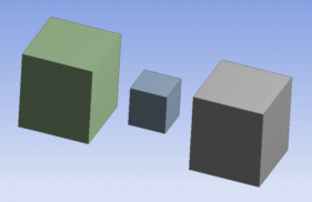
Example 80: Scaling about centroids
The selected bodies will undergo a scaling operation about their centroids:
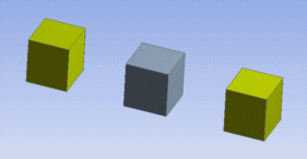
The bodies after scaling them about their centroids by a scale factor of 2x: