


The following topics are discussed:
- 9.2.4.1. Creating a Radial Pump Impeller
- 9.2.4.2. Initial Design Parameters - Radial Pump Impeller
- 9.2.4.3. Initial Angle/Thickness Parameters
- 9.2.4.4. Optimizing the Meridional View
- 9.2.4.5. Define the Blade Shape at the Hub and Shroud in the Meridional View
- 9.2.4.6. Define the Inlet and Outlet Sections
- 9.2.4.7. Adjust the Blade Angles at the Hub in the Angle View
- 9.2.4.8. Define the Blade Thickness Profile
- 9.2.4.9. Prescribe the Leading/Trailing Edge Ellipse
- 9.2.4.10. Utilizing the Information in the Auxiliary View
- 9.2.4.11. Saving Your Model
The following procedure can be followed as an example of using BladeGen to create a Radial Pump Impeller from start to finish.
BladeGen allows the user to create a blade system from scratch, using one of six standard initial configuration types. For this example, a Radial Impeller is used.
Select the File | New | BladeGen Model menu command or
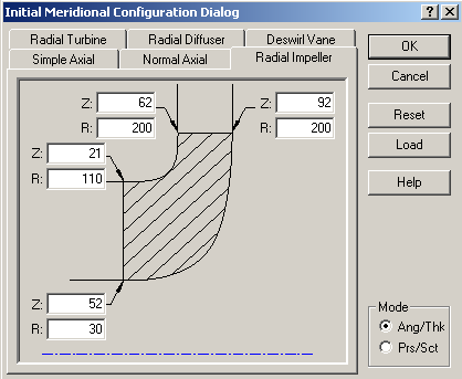
 toolbar button which will display the Initial Meridional Configuration Dialog (shown in Figure 9.89: Initial Meridional Configuration Dialog).
Select the Radial Impeller tab
Enter the parameters for the initial blade layout as shown in Figure 9.89: Initial Meridional Configuration Dialog.
Be sure to select Ang/Thk mode in the bottom right corner.
Press Enter or select the OK button to continue
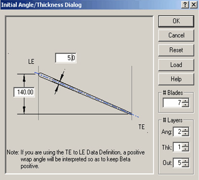
Using Figure 9.90: Initial Angle/Thickness Dialog, the initial blade parameters are completed:
Enter the nominal wrap angle of 140 degrees, thickness of 5 and 7 blades. Normally, BladeGen sets the leading edge theta to zero.
Press Enter or select the OK button to display the BladeGen Window.
The most critical operation in the meridional view is to define the shape of the hub and shroud curve. The endpoints for these curves were specified when Initial Design Parameters were entered in the Initial Meridional configuration dialog.
The hub and shroud profile for this case are well defined automatically. In this case, there is no need for any additional modifications.
The hub and shroud definitions up and downstream of the blade can be defined when the user will be performing CFD analysis on the proposed design. It is also nice to set the inlet and outlet sections to reasonable values to make the BladeGen model represent the final design. To set the position of the inlet and outlet points:
Double click the shroud inlet point at the top left of the meridional view.
The Point Location Dialog will open. The Horizontal value is the Axial location (Z co-ordinate) and the Vertical value represents the Radius.
Enter -10 and 110 for the horizontal and vertical values. Click OK.
Double click the hub inlet point (bottom left corner) and enter -10 and 25 for the horizontal and vertical values. Click OK.
Double click the hub outlet point (top right corner) and enter 91 and 250 for the horizontal and vertical values. Click OK.
Double click the shroud outlet point (top left corner) and enter 63 and 250 for the horizontal and vertical values. Click OK.
The following topics are discussed:
The meridional profile is now defined and the Blade angles can be set. In the Angle View, the active layer is indicated by a red dot in the layer column on the right-hand side. By default, the hub layer is active. Once the Hub angles are set, the Shroud layer can be activated by left-clicking the black dot at the top of the layer column.
The blade angles can now be defined as follows:
Right-click in the Angle view and select Adjust Blade Angles
In the Leading Edge tab, enter 35° for the Tangential Beta value, the Beta value will automatically be updated as 90° minus Tang. Beta. Leave all the other values at zero.
In the Trailing edge tab, enter a Theta angle of 137.5° and enter 22.5° for the Beta value. The Tangential Beta value will be automatically updated as 67.5°. All other values can remain as zero.
Close the Blade Angle Dialog by selecting OK
The Theta curve will be automatically switched to a Bezier segment with 6 control points.
Left-click the black dot located at the top of the layer column to activate the Shroud layer. The blade angles can now be defined as follows:
Right-click in the Angle view and select Adjust Blade Angles
In the Leading Edge tab, enter 13.5° for the Tangential Beta value, the Beta value will automatically be updated as 90° minus Tang. Beta. Leave all the other values at zero.
In the Trailing edge tab, enter a Theta angle of 138.5° and enter 22.5° for the Beta value. The Tangential Beta value will be automatically updated as 67.5°. All other values can remain as zero.
Close the Blade Angle Dialog by selecting OK
The Theta curve will be automatically switched to a Bezier segment with 6 control points.
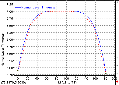
At this time, the Blade thickness can be defined in the Thickness view. For this example, a ‘parabolic’ style will be applied as shown in Figure 9.91: Blade Thickness Profile. Since it is easier to control fewer numbers of points, we can start by making the profile curve a spline with 3 control points and add further details after we have obtained the basic shape.
Make the Hub layer active in the Thickness view by left-clicking the black dot at the bottom of the layer column.
Right-click the mouse and select Convert Points to.. Spline Curve Points…
In the Point Count Dialog, enter 3 points and select OK.
Double click the leading edge point and enter a thickness value of 4.9mm.
Double-click the trailing edge point and enter a thickness value of 4.8mm
Double-click the middle control point and enter a thickness value of 7.0mm
Right-click the mouse and select Zoom Fit
Now that the basic shape is defined, we can add points, split curves and refine the profile to achieve the desired shape. In this case, we will simply increase the number of control points to achieve the desired profile:
Right-click the mouse and select Convert Points to.. Spline Curve Points…
In the Point Count Dialog, enter 5 points and select OK.
Adjust the curve point locations more closely resemble the image in Figure 9.91: Blade Thickness Profile, don’t worry about getting it exact at this point, more control points will still be added.
Right-click the mouse and select Convert Points to.. Spline Curve Points…
In the Point Count Dialog, enter 8 points and select OK.
Adjust the curve point locations more closely resemble the image in Figure 9.91: Blade Thickness Profile, at this point, you should be able to achieve the desire profile.
Starting at 3 control points, setting the profile and gradually increasing the number of control points makes creating the desired profile easier to achieve than simply adding 8 points from the very beginning.
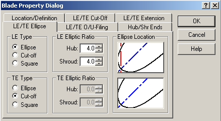
Select Blade | Properties menu commands or the ![]() toolbar button located on the left hand side of the BladeGen window to set the blade properties. Set the Leading Edge/Trailing Edge Ellipse tab, adjust the values as shown in Figure 9.92: LE/TE Ellipse Settings. All other values can remain unchanged.
toolbar button located on the left hand side of the BladeGen window to set the blade properties. Set the Leading Edge/Trailing Edge Ellipse tab, adjust the values as shown in Figure 9.92: LE/TE Ellipse Settings. All other values can remain unchanged.
The most common use of the auxiliary view is to display the rendered 3D view as shown in the first tutorial. There are many other functions available for this view. At this point, you may wish to review the Auxiliary View Details and experiment with the different Auxiliary View options.
Upon exiting BladeGen, the blade model is automatically saved to a file associated with the Workbench project. You must save the project before closing it in order to retain the project files. You can save the project from the Workbench interface as usual. You will be prompted for a project name if you have not previously saved the project. The File | Save menu command (Save ![]() toolbar button) can function as an alternative way to save the project; see Saving a Blade Model for details.
toolbar button) can function as an alternative way to save the project; see Saving a Blade Model for details.