


The following topics are discussed:
- 9.2.5.1. Creating an Axial Turbine Blade
- 9.2.5.2. Initial Design Parameters - Axial Turbine Blade
- 9.2.5.3. Initial Angle/Thickness Parameters
- 9.2.5.4. Setting Model Properties
- 9.2.5.5. Optimizing the Meridional View
- 9.2.5.6. Defining the Inlet and Outlet Sections
- 9.2.5.7. Adjusting the Blade Angles at the Shroud in the Angle View
- 9.2.5.8. Adjusting Blade Profiles at Mid-span Locations
- 9.2.5.9. Adjusting the Hub Blade Angles
- 9.2.5.10. Defining the Blade Thickness Profile
- 9.2.5.11. Prescribing the Leading/Trailing Edge Ellipse
- 9.2.5.12. Adding Custom Output Layers
- 9.2.5.13. Saving Your Model
The following procedure can be followed as an example of using BladeGen to create an Axial Turbine blade from start to finish.
BladeGen allows the user to create a blade system from scratch, using one of six standard initial configuration types. For this example, a Normal Axial template is used.
Select the File | New | BladeGen Model menu command or
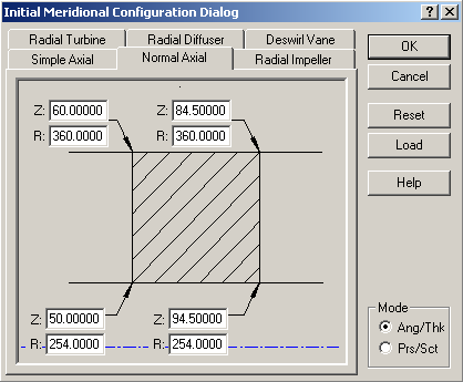
 toolbar button which will display the Initial Meridional Configuration Dialog (shown in Figure 9.93: Initial Meridional Configuration Dialog).
Select the Normal Axial tab
Enter the parameters for the initial blade layout as shown in Figure 9.93: Initial Meridional Configuration Dialog.
Be sure to select Ang/Thk mode in the bottom right corner
Press Enter or select the OK button to continue
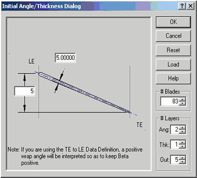
Using Figure 9.94: Initial Angle/Thickness Dialog, the initial blade parameters are completed:
Enter the nominal wrap angle of 5 degrees, thickness of 5 and 83 blades.
Press Enter or select the OK button to display the BladeGen Window.
Set the model properties as follows:
Select Model | Properties from the main menu.
Set Component Type to Turbine.
Set Configuration Type to Axial.
Set Model Units to MM.
Click OK.
The most critical operation in the meridional view is to define the shape of the hub and shroud curve. The endpoints for these curves were specified when Initial Design Parameters were entered.
The following topics are discussed:
The hub and shroud definitions up and downstream of the blade can be defined when the user will be performing CFD analysis on the proposed design. It is also nice to set the inlet and outlet sections to reasonable values to make the BladeGen model represent the final design. To set the position of the inlet and outlet points:
Double click the shroud inlet point at the top left of the meridional view
The Point Location Dialog will open. The Horizontal value is the Axial location (Z co-ordinate) and the Vertical value represents the Radius.
Enter 40 and 360 for the horizontal and vertical values. Click OK.
Double click the hub inlet point (bottom left corner) and enter 40 and 254 for the horizontal and vertical values. Click OK.
Double click the hub outlet point (bottom right corner) and enter 110 and 254 for the horizontal and vertical values. Click OK.
Double click the shroud outlet point (top right corner) and enter 110 and 360 for the horizontal and vertical values. Click OK .
By default, BladeGen creates the blade’s hub and shroud curves as curves with 5 control points. For this example, a single straight edge is required. Therefore, we can convert this curve to two control points.
Left-click the blade’s hub curve.
Right-click the mouse and select Convert Points to.. Spline Curve Points…
In the Point Count Dialog, enter 2 points and select OK.
Repeat this procedure for the blade’s shroud curve.
The following topics are discussed:
The meridional profile is now defined and the Blade angles can be set. In the Angle View, the active layer is indicated by a red dot in the layer column on the right-hand side. Make the Shroud layer active by selecting the black dot at the top of the layer column. It will turn red and the Shroud is now active.
The blade angles can now be defined as follows:
Right-click in the Angle view and select Adjust Blade Angles
In the Leading Edge tab, enter a Beta value of -4.65°. The Tang. Beta value will be updated automatically to a value of 90° minus Beta.
Enter a Theta value of -2.5°.
In the Trailing edge tab, enter a Beta value of 70.10°. The Tangential Beta value will be updated automatically to a value of 19.90°.
Enter a Theta value of 2.15°
Leave all other values set to zero.
Close the Blade Angle Dialog by selecting OK
Setting the blade angles did not create a suitable profile. Modify the Beta curve as follows:
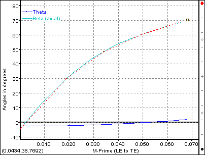
Right-click in the Angle view and select Beta Definition
Right-click the mouse a second time in the Angle view and select Convert Points to.. Spline Curve Points…
In the Point Count Dialog, enter 5 points and select OK.
Modify the control points by dragging them with the left mouse button so that the beta curve looks similar to Figure 9.95: Shroud Beta Profile.
The following topics are discussed:
It is often desirable to control the blade shape at more than just the hub and shroud locations. To control the blade profiles at more locations, additional Layers can be activated or generated. In this example, the layer generated at a span location of 0.5 will be used.
Right-click in the Angle view and select Layer Control.
Click the empty box to the left of Span 0.500 to select the layer.
Select OK.
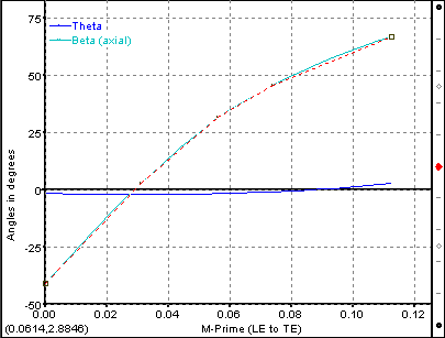
Make the new layer active by selecting the new black dot at the mid-span location of the layer column. After you have selected it, the dot will turn red. Repeat the procedure defined earlier using Figure 9.96: Span=0.5 Beta Profile as a guide. For the Blade Angles:
In the Leading Edge tab, enter a Beta value of -40.7° and a Theta value of -1.5°.
In the Trailing edge tab, enter a Beta value of 66.88° and a Theta value of 2.74°.
Make the Hub layer active by selecting the black dot at the bottom of the layer column. After you have selected it, the dot will turn red. Repeat the procedure described earlier using a leading edge Beta value of -67°, a leading edge Theta value of 0.5°, a trailing edge Beta value of 42°, and a trailing edge Theta value of 3.33°.
The following topics are discussed:
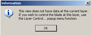
By default, BladeGen assumes that the blade thickness profile is uniform from hub to shroud. If you try to make some thickness modifications at any layer other than the hub a warning message as shown in Figure 9.97: Inactive Layer Warning appears.
If the blade thickness is to be non-uniform from hub to shroud, additional layers must be activated as follows:
Right-click in the Thickness view and select Layer Control…
In the Layer Control Dialog, check the box beside the layer at Span: 1.000 and Span: 0.500.
Select OK.
Define the Blade Thickness at the Shroud:
Click on the black dot at the top of the Layer Column in the Thickness view to make the shroud layer active.
Convert the thickness curve to a 3-point spline. Right-click the mouse in the Thickness view and select Convert Points to.. Spline Curve Points…
In the Point Count Dialog, enter 3 points and select OK.
Set the Leading edge thickness to 1.25mm by double-clicking the leading edge point and entering a thickness of 1.25mm.
Set the Trailing edge thickness to 0.50mm.
Double-click the middle point and set the thickness to 3.25. Also adjust the Meridional position by setting the M value to 9.
Now, extra control points can be added to create the profile as shown in Figure 9.98: Shroud Thickness Profile:
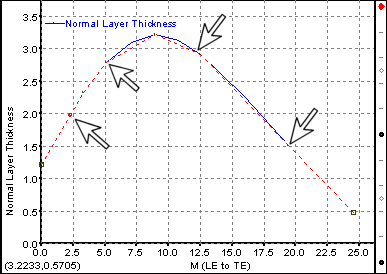
Right-click the mouse in the Thickness view and select Segment Operations.. Insert Many Points…
Click the left mouse button near each of the locations indicated by the black arrows in Figure 9.98: Shroud Thickness Profile.
After you have added all 4 points, Right-click the mouse and select Segment Operations.. Insert Many Points… again to finish adding points.
Click and drag the newly-added points to the locations indicated by the arrows in Figure 9.98: Shroud Thickness Profile.
Click on the black dot in the middle of the Layer Column in the Thickness view to make the span 0.5 layer active.
Convert the Thickness curve to a spline with 3 Control Points.
Set the Leading Edge to 1.1mm thickness, trailing edge to 0.5mm and the middle control point to a thickness of 5.5 at a Meridional distance of 9.0
Create 4 extra control points as described earlier to create a similar profile as shown in Figure 9.98: Shroud Thickness Profile.
Click on the black dot at the bottom of the Layer Column in the Thickness view to make the hub layer active.
Convert the Thickness curve to a spline with 3 Control Points.
Set the Leading Edge to 1.0mm thickness, trailing edge to 0.5mm and the middle control point to a thickness of 6.5 at a Meridional distance of 18.
Create 4 extra control points as described earlier to create a similar profile as shown in Figure 9.98: Shroud Thickness Profile.
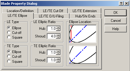
Select Blade | Properties menu commands or the ![]() toolbar button located on the left hand side of the BladeGen window to set the blade properties. Set the Leading Edge/Trailing Edge Ellipse tab; adjust the values as shown in Figure 9.99: LE/TE Ellipse Settings. All other values can remain unchanged.
toolbar button located on the left hand side of the BladeGen window to set the blade properties. Set the Leading Edge/Trailing Edge Ellipse tab; adjust the values as shown in Figure 9.99: LE/TE Ellipse Settings. All other values can remain unchanged.
The following topics are discussed:
A layer (streamline) is defined as a meridional curve that represents surface of revolution. So far, layers have been used to control the blade angles and thickness profiles. Layers are also used for controlling the output from BladeGen. For more detailed information, see Layer Details .
Right-click the mouse in the Angle View and select Layer Control… from the pop-up menu.
Select the Output tab and click the Create button.
In the Layer Dialog, enter a span value of 0.05 and click OK.
Repeat this procedure for span values of 0.1 and 0.125.
Click OK to close the Layer Control Dialog.
Layers can also be generated at variable span locations as follows:
Right-click the mouse in the Angle View and select Layer Control… from the pop-up menu.
Select the Output tab and click the Create button.
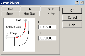
In the Layer Dialog, click the Shr Gap tab and enter LE gap of 90.125 and a TE gap of 86.95 as shown in Figure 9.100: Layers at Non-Uniform Span Locations. Click OK.
Click OK to close the Layer Control Dialog.
Upon exiting BladeGen, the blade model is automatically saved to a file associated with the Workbench project. You must save the project before closing it in order to retain the project files. You can save the project from the Workbench interface as usual. You will be prompted for a project name if you have not previously saved the project. The File | Save menu command (Save ![]() toolbar button) can function as an alternative way to save the project; see Saving a Blade Model for details.
toolbar button) can function as an alternative way to save the project; see Saving a Blade Model for details.